Tell me if im wrong but once you adjust the runout of the probe wouldnt you want to mark the probe and spindle so everytime you use it they index the same way. The way it shows in the video you are correcting for runout of the probe and of the spindle. If the spindle had say 0.0003 to 0.0005 runout and you put the probe back in 180degs out now you have runout again
This can certainly be done like you say and it will be more accurate if your plan is to chase tenths. It’s also important to put this into perspective when compared to the step resolution and linear accuracy of MR-1 which, when measured together, is in thousandths not tenths.
2 Likes
Thanks for the feedback mines due to show up this coming Friday. Looking forward to it.
1 Like
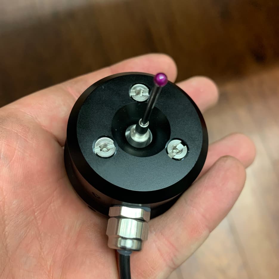
Went through probe run out routine with the fial indicator.
Got it to within .0005 tun out.
Then imagine to my surprise the next time I goto mount it and I check it and I have a run out on the ball of +/- .001 so .002.
The collet does not seem to give you the accuracy you are looking for if you remove the probe and reinstall it.
I can center up a 4 jaw chuck in a lathe just fine and used similar process on the probe.
Tried it multiple times while checking another issue. It is easy to index the probe because there is a wire ciming out the side of it so you can clock it to 3 o’clock or whatever you like.
My bigger issue is that I cannot get the probe to come back to the centerline of a part.
Squared off some stock and tested the probe. After the routine is done I came back with a .250 end mill. Moved the end mill to .125 off both the X/Y axis to run it down the part.
I have roughly .007 of stock being removed after supposed zero by the probe.
Tried playing with the shaft linear flex setting and went both bigger/smaller without seeing the effect that I was hoping for.
Setting the linear flex to .001 I managed to get the X axis to a smaller amount of deviation but the Y axis deviation got larger. I wound up watching the set screws and trying to keep them oriented to the axis of travel, at one point that got my X to within .001 at one point but the Y was way worse.
So I ran the test again, mounted probe and tested with the set screws rotated 45 degrees off from one another. Doing test cut with .250 end mill backed off .125 on X/Y resulted in roughly .006-.007 being removed from both axis.
If it were only .001 or nothing I would be happy. Maybe .002 if I was not putting the probe on an indicator to test runout or adjust it.
1 Like
You will need to etch the collet or find a locating mark to keep the runout the same with the probe. Interesting your probe locations are so off. Is it taking material evenly from top and bottom?
1 Like
Regarding probe tip runout, to achieve the best result you need to apply match marks to the probe, the collet, and the spindle. Those marks need to be aligned when you first true the tip and any time you remove/replace the probe. You should see an improvement in the runout when doing that.
Regarding the accuracy errors you are seeing, thats wildly out of spec for these probes. As an example, we occasionally run a calibration sequence where the probe tip senses around the perimeter of a 1/2" gage pin in 10 degree increments (radial moves toward the center of the pin). We then take the XY points from that test and do a least squares analysis to determine best fit circle. From there we look at maximum deviations of the individual points to the best fit circle. Routinely all points are under .001" delta with the occasional point or two a hair over .001". Keep in mind that backlashes and motion errors are accumulated into those errors as well.
In short, its safe to say that you have a mechanical issue with your probe in particular- likely an assembly issue. I recommend trying the following steps and then check the probe to see if there’s an improvement:
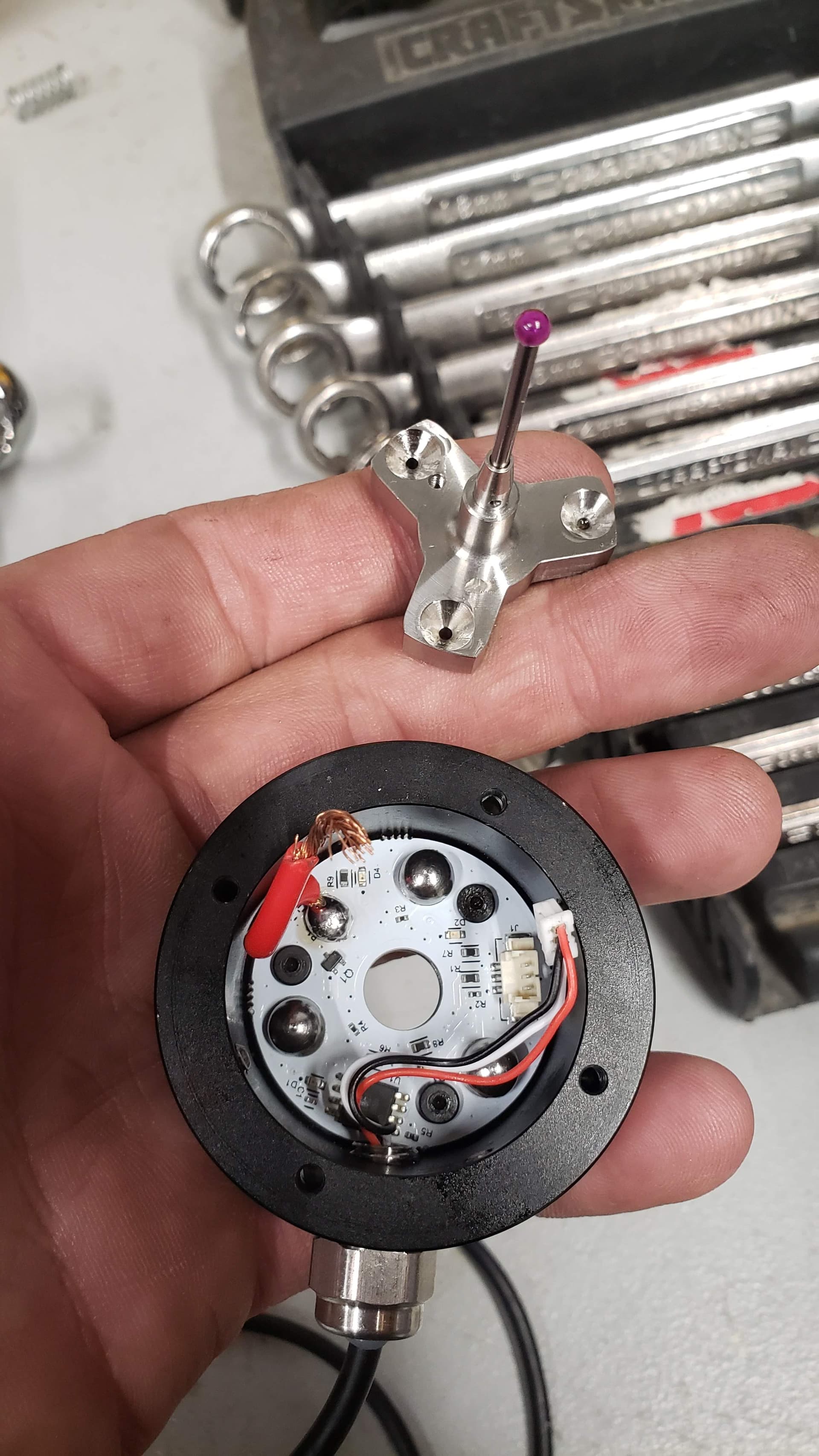
- Use a flathead screwdriver and break loose the three slotted nuts on the bottom of the probe. Just crack them loose but do not remove them.
- Very slightly tighten each nut to simply take out the lash from each one.
- Progressively snug each nut further using the screwdriver. Do not tighten these screws much, they only need to be snugged down.
1 Like
Honestly thinking of jist going back to a wiggler for edge finding and zero.
Looking at the way some of the 3 leg edge finders work I can see how this issue can come about based on the angles that cause a leg to tip off the bearings breaking continuity.
That or I will be using a very specific face/leg of the probe for coming into contact on X/Y axis while I test for consistency.
/edit
Was posting as the post above was generated.
I researched how these things worked last night and I will be toying with it more today as I make some pieces to test it against. The three screws on the bottom were exactly where I will be heading today while I start to try to figure this thing out and why it is so off.
I hope guys with probe repeatability issues follow your advice here. Loosening and retightening these fasteners allows the ball & sockets of the probe to seat perfectly. When I first had received my replacement probe, I could “shift” the probe tip before it lifted off one of the ball socket seats. Loosening and tightening these fasteners made all the difference. I now have regular repeatability <0.001". Sometimes it helps to understand the inner workings!
2 Likes
I am having the same issues, i ended up recentering the probe with a mic on every use. I can zero something 3 times in a row after recentering and have each zero be 7 to 15 tho different, but am very much considering just going back to the wiggler, very disappointed in the probe, I’ve compared it to the wiggler and it doesn’t hold up to the consistency or reliability in any shape way or form.
Did you loosen the bottom slotted nuts & then rock the tip around to ensure the ball/sockets are seated? The other thing you could do it remove some of the thick grease from the ball/sockets as well. Either way, you should not be seeing .007 - .015" difference.
I ended up taking advice from this form every ones experience, I took it completely apart, centered the pcb, took the other half of the assembly to my lathe and guaranteed the run out (it was not very far off a few tenths maybe, no cuts required) took the grease off, centered the nut things on the bottom, got a collet just for it, witnessed marked the probe, the collet, and where the nut it torqued to and a small one on the spindle shaft. Cut the red wire a bit since it was shoved in-between the wall and the stylus holder added a proper wire clamp. and replaced those little miniature set screws with thumb screws for easier adjustment.
Is this excessive… maybe
But I went from my guage spinning around everytime the probe was breathed on wrong to about 5 tenths, I still adjust it each time but im not chasing it around like before