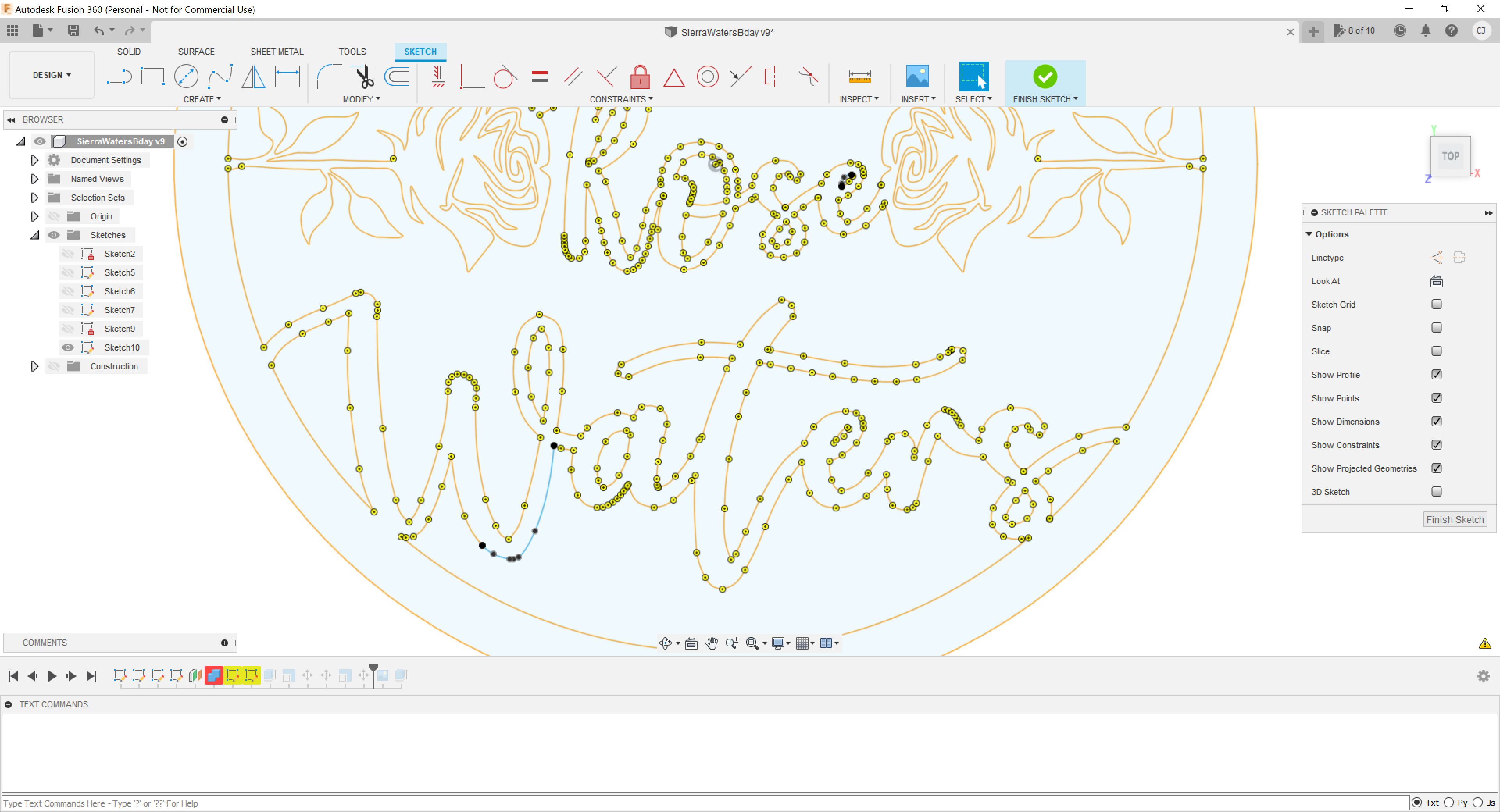
I included the file. It works without lead-ins and lead outs. It’s got plenty of room for a lead in and I’ve tried everything. In the setup the toolpath I’m concerned about is labeled “this is broken” I do want to run a lead in for this path. Tried making it smaller, setting a point. I’ve googled the crap out of this and I’ve been at it for several hours now. The part that won’t generate is under “waters”.
EDIT - says new users can’t upload files. I can email it if anyone wants to help. Its a fusion 360 .f3d file.
Enabled feature flags: online-system-library setup-sheet-viewer tool-library-v4-release
Warning: Toolpath generation was aborted by user.
Warning: One or more passes were discarded due to linking constraints.
Warning: No passes to link.
Generation completed with 2 warning(s) in 5.3s.
Warning: Empty toolpath.
Send it to derrick@fortifyfabworks.ca
Check the lines down there. I’d bet something isn’t connected (try the Waters bottom profile first). Grab the Sketch Checker add-in from the Fusion add-in manager. You should be able to find the broken lines easily that way.
Thanks Fortifyfabworks. I sen tthe email a little bit ago.
James, I installed the plugin but I’m not sure it does anything at the moment. Still messing with it. Could be that something isn’t connected but I’ve gone over it zoomed way in a few times now and it selects OK. I’m fairly new to fusion and this is the first real thing I’ve really created.
Thanks for the quick replies guys!
The design is fine. The biggest issue is the roses is where your running into the issues.
Its where the lines of the roses are connected into the large part.
If you cut that off from the large portion and just make a cut out instead of having it all connected it should work better.
Do you have a clean dxf of the sketch by any chance?
So I’m pretty new to this and I didn’t do the sketch all at once. So what happened was that I extruded a bunch of different bodies at different heights, then combined them, then created a projected sketch with an offset plane to come up with what I have. What I sent is really all I have here. When I go to create tool paths, the roses and everything comes out fine except the part under the waters. I can’t create a tool path for just that at all.
I don’t think the sketch checker is working because its a projected sketch mostly except the few lines I decided to change up. It definitely wasn’t building a tool path with it before I modified those lines and it is building a tool path in the other spot I modified so I don’t think that’s the issue. Also, if I don’t have lead ins it does still seem to build the tool path. Same thing if I do an open contour and cover like 95% of the path. Seems super weird to me.
He said it was the part under the Waters word. Are you finding an issue with the roses? (I initially suspected those because of the tight angles but I went with what he reported.)
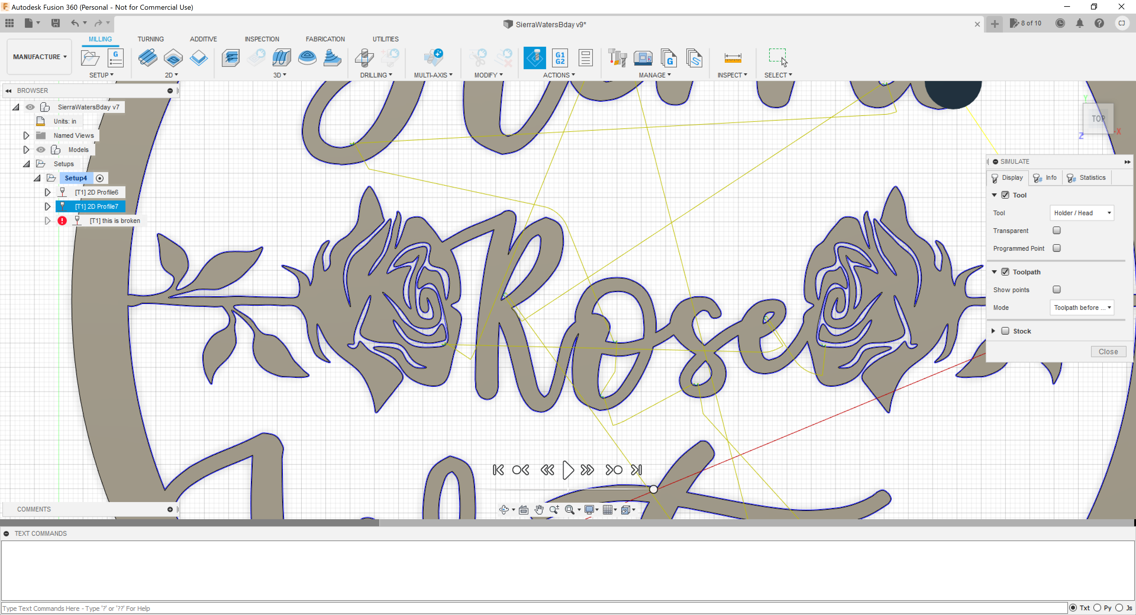
Here is an example of the simulate with two of the toolpaths set. It’s about 2x2ft so i’m hoping it’ll cut it ok but i’m still in the trial and error phase of learning all this stuff.
The sketch is fine there’s no broken lines.
Its just hard to do anything with what you have cause there’s so many sketches and bodies and components and I’m not sure what you have going on.
I’ll look a little more.
Yeah, sorry. I’ve been screwing with it so long now I’ve made a bit of a mess. Doesn’t help that i’m new to this! Thank’s for looking, you’re saving my butt here!
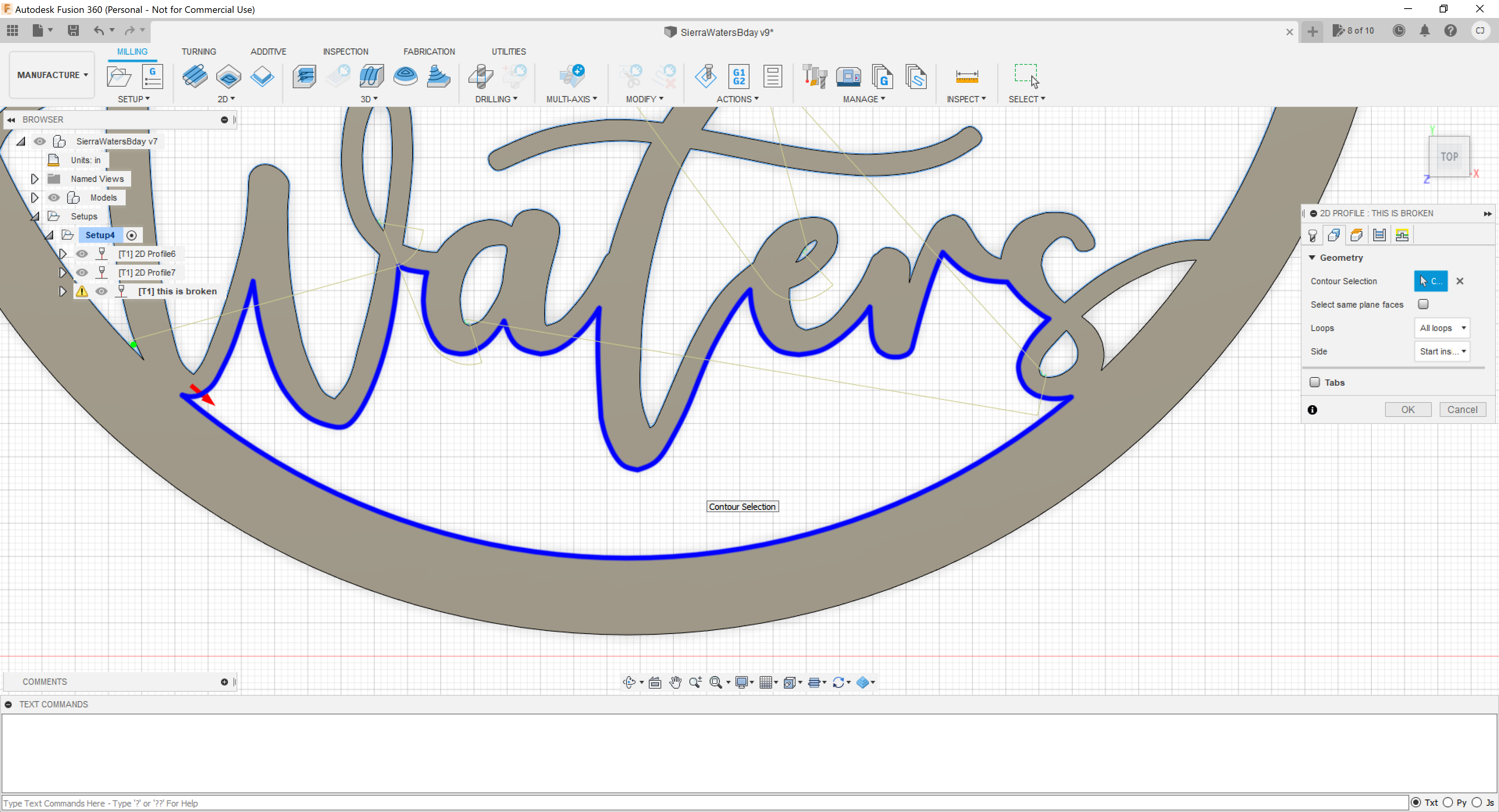
This is the exact spot I’m having trouble with. Oddly it works with no lead in or leads outs and pierce clearance set to zero.
Set it to roll around corners
It is, still not working. Tried messing with all sort of combinations of settings.
I’m still looking at it.
This happened to someone else on here recently I’m not sure if he figured it out or not either.
I’m not really sure what the issue is. It might be a contour issue with a recent fusion update since this is the second time I’ve seen something like this recently but I’m not sure.
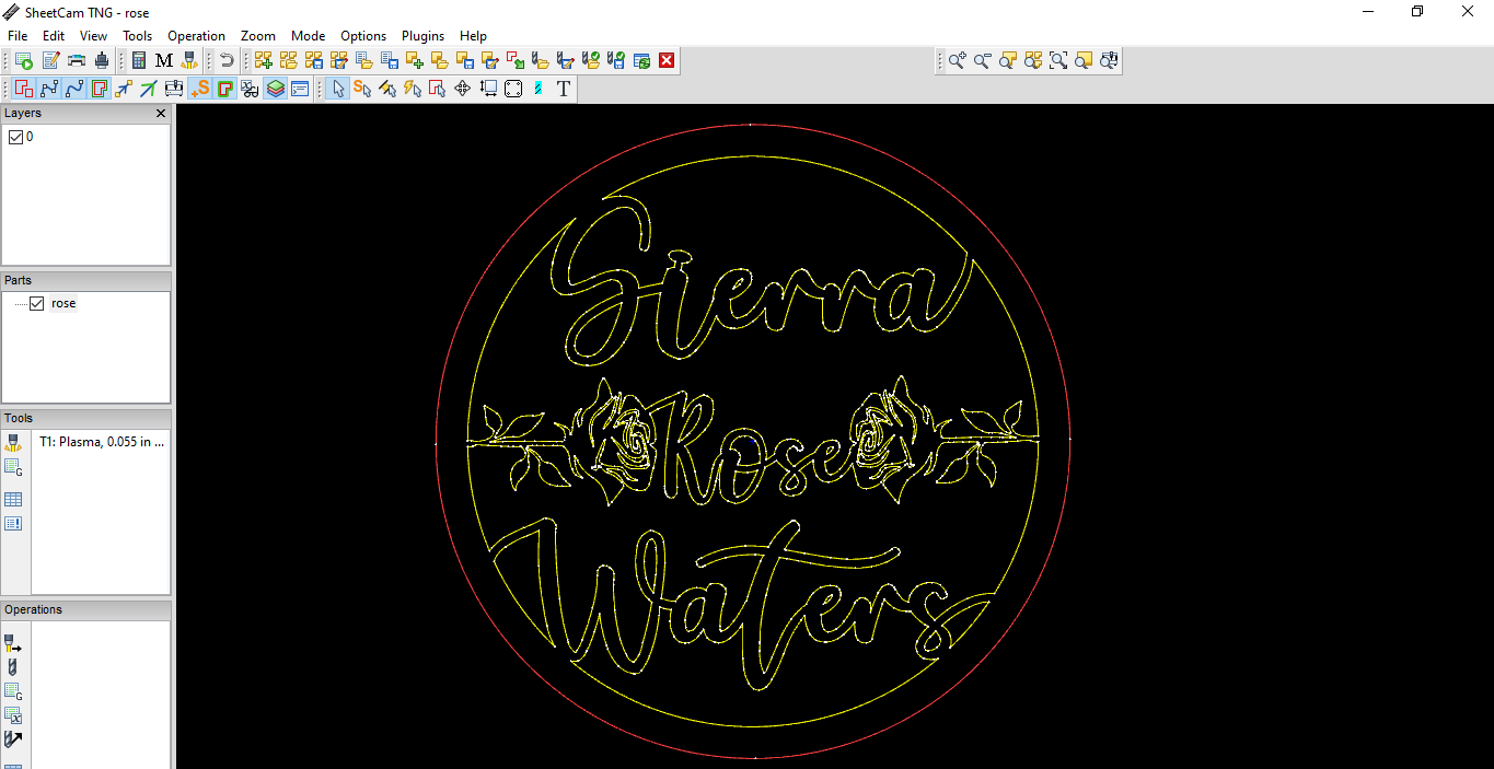
Sheetcam generates a cutpath with only one warning and that’s just it can’t fit a lead in on some parts.
And here’s a clean dxf sketch if anyone else wants to give it a try
rose.dxf (614.8 KB)
I’ll redraw it in an svg for a fee, pm me if you’d like.
I started from scratch and totally redid this. Same problem in the same spot… sweet. Thanks for trying to help Fortify. I’m not about buying more software right now so I’m not sure what I’ll do.
I got it just give me a second just double checking.
1 Like
Try this one.
Sierra Rose.dxf (616.9 KB)
1 Like
Any idea what you did? It works on the outside loop with a leadin but not on the inside still. For me at least. lead in radius is just .03 and distance .03, 60 degree. keep nozzle down. Pierce Clearance is .026. Sideways compensation left, in computer, roll around corners. Did you do something different?
Also, thanks for spending time on this with me. I’ve not stood up in about 10 hours. Totally redid this and changed the bottom up a fair bit and it still is happening (on my other one)
I’m still trying to get the one you just sent me to work.