Got it running now. I’ll cut it tomorrow. That wasted a solid 10 hours of my day with this buggy software.
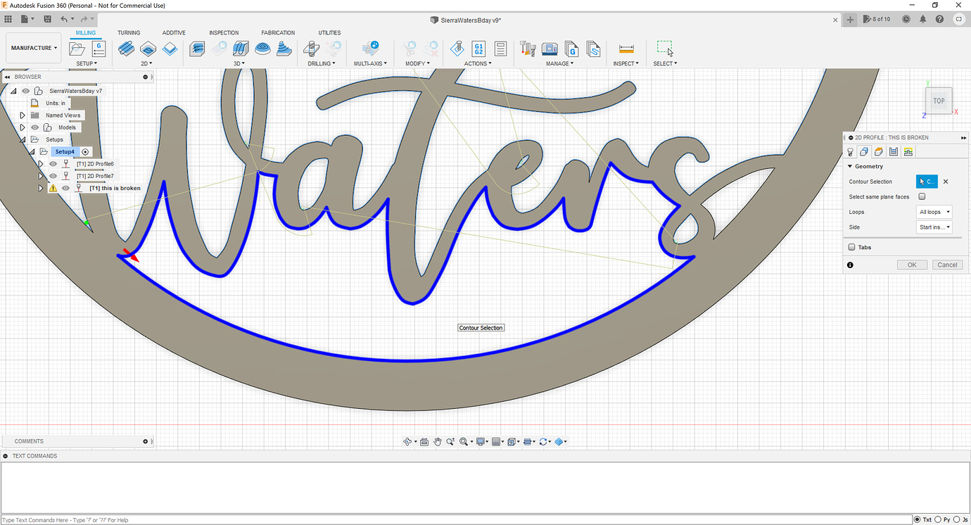
What changed is that I had to round out under the W and under the S. Why? I have no clue cause it cuts in much tighter spots and turns than that in many other places…
Also, I’m not sure why, but I have to split it up into 3 tool paths or it just sits trying to calculate around 95%.
Thanks to everyone that helped. I’ll send you some money tomorrow Fortify for your time.
I’d upload the final dxf but it still says I’m too new. If anyone wants it I’ll email them.
All good I’m not worried about that.
That’s all I did and it generated a cut path. There’s something weird going on with the lines in the W and S in those tight corners because if you delete those two lines and redraw them it generates a cutpath with those tight corners.
This probably isn’t much of a help, but I had the exact same problem and the only way I could fix it was to import the image into Inkscape (free vector drawing tool) trace it all out a new. Minimize ALL vector points to the absolute minimum (basically I went back in and joined points till just before it distorted the drawing). Reimport it back into Fusion and then I never had the problem again. My guess is that Fusion isn’t as good with vector points as say an InkScape or a true vector drawing program. This is just a total guess, but seems like it tries to simulate but doesn’t always get it right. Unrestingly enough I actually tried it on 2 different computers with Fusion 360 and got different results. It was only on the laptop that I had hooked to the CNC that it wouldn’t simulate cut a section just like this. That is until after I redrew it in Inkscape. Now if I’m going to do text or a sign of ANY kind I do it in Inkscape first then to fusion then out to gcode.
Fusion is an amazing program, but I think even Autodesk would probably tell you it’s not a vector drawing program. I base this on the fact that they actually have a different program for just about every type of creating. Each one with it’s own strengths and weaknesses. Maya, AutoCad,Sketchbook and the like.
Also as a side note Fonts in general never create complete vector paths. This is usually why you have to use a Font that is made for CNC cutting. What they really mean by “made for” is that somebody went in to the font and edited every letter so that it actually closes the letter off. I found with almost every normal font it leaves vector shapes open at even a microscopic level that you have to go in an close.
Some time ago Fusion 360 had an update and it broke on some tool paths. I forget what update it was but it happened on one of my drawings. Created a path before update. Couldn’t create path after update with no changes to the file.
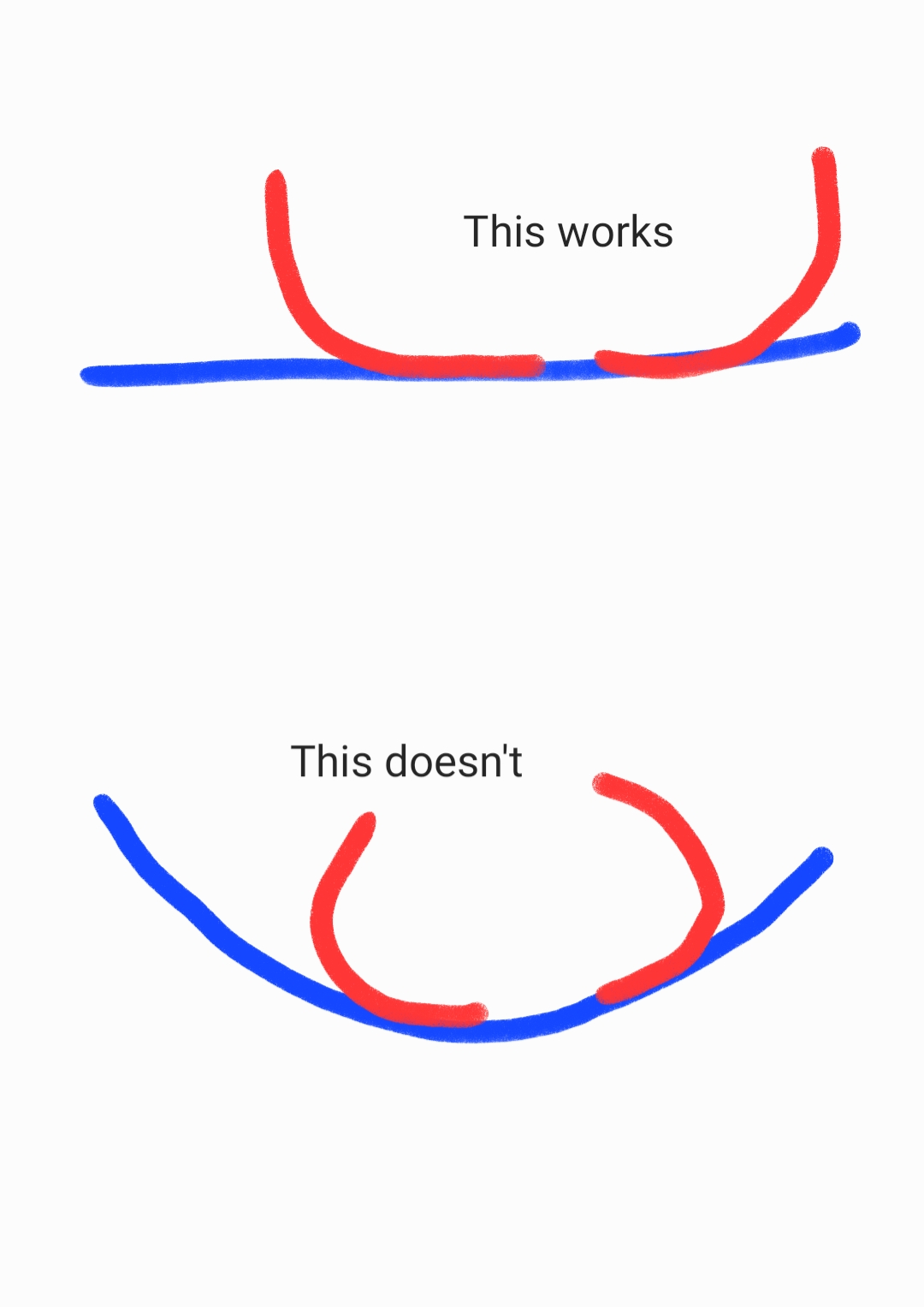
Mostly curves/curved with no straight lines. I think this happens when lead in/out radius would be greater/less then that of the defined radius. Although it doesn’t happen on circles.
This is what I think might be happening. Same 90 degree lead in/out on straight line and curved line but the curved lead in/out is more like 120 degrees when generated.
My only work around from what I remember was to get rid of the lead in and out and increase my pierce clearance to act as a lead in. Or to get rid of all 3.