Just posted this on Plasma Spider, but thought I’d post it over here as everybody has been so helpful.
Running it on a machine torch from a RC 45. Table is a Langmuir Crossfire. Cut height is set to -0.1, 100ipm.
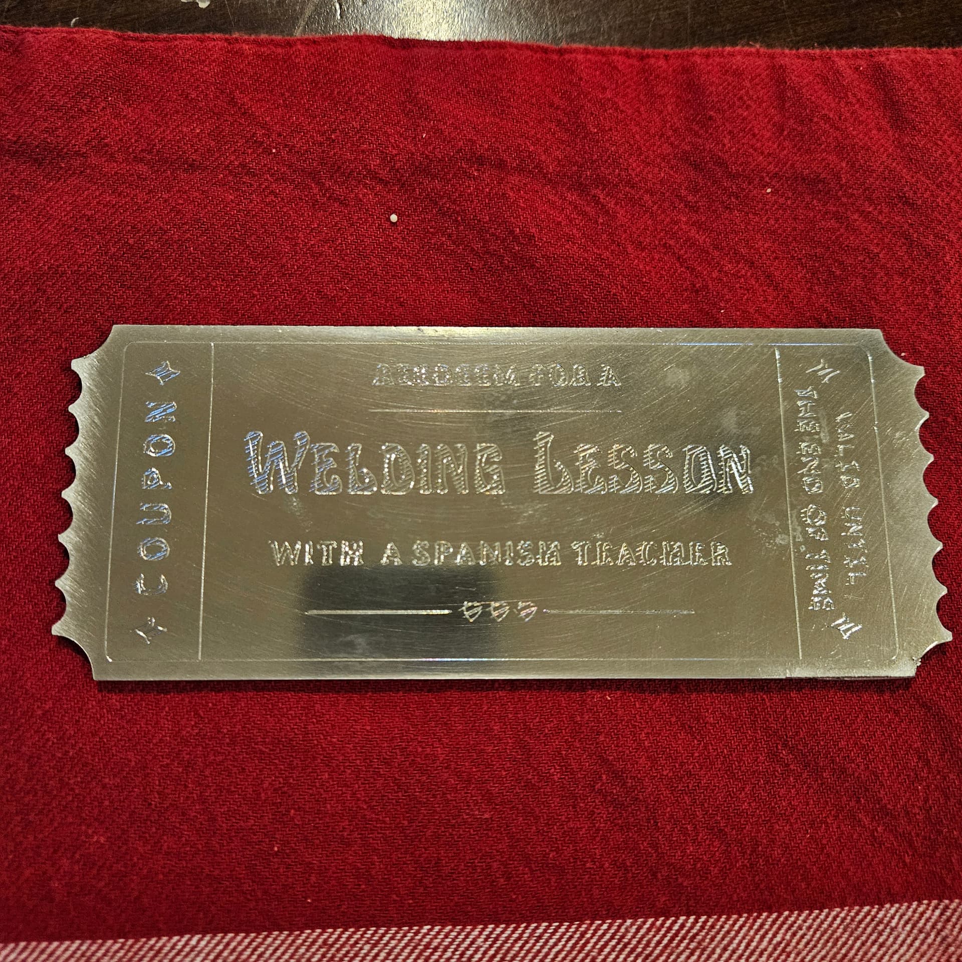
Lines were drawn with AxiDraw in Inkscape (want to say .031 spacing maybe?), looked good in the svg when loaded into Fusion, looked good in the CAM process. Maybe the metal moved (look at the ‘s’ in “lesson”), but I had it weighted down as best I could.
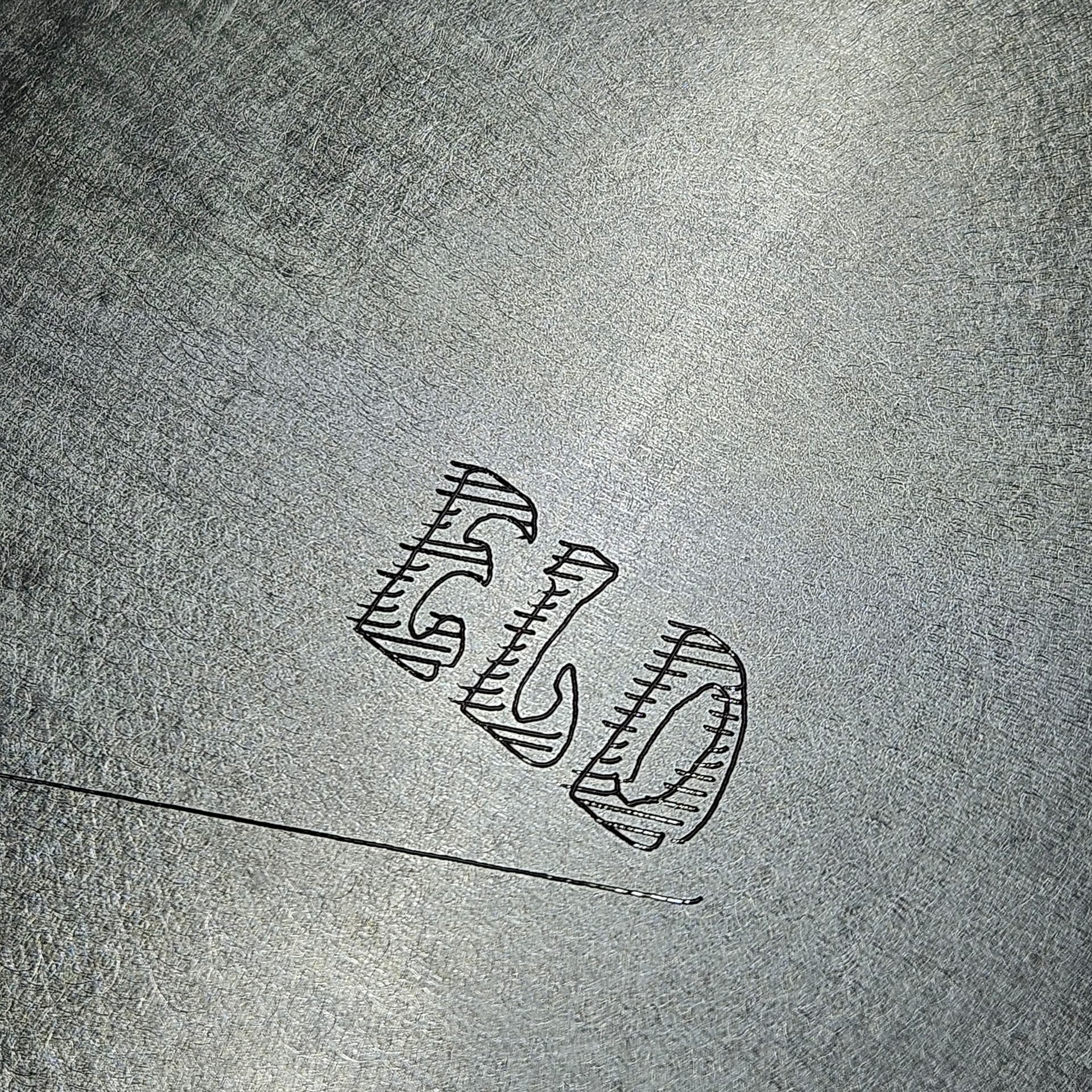
I don’t think the problem is the workpiece moving. The hatches look uniformily messed up. I think your timing on lowering the scribe and contacting the metal is off. I would run some experiments just filling some simple rectangles and adjusting plunge rate, ‘pierce delay’, and actually ‘cut’ height. The probe only needs about 1/32-1/16 of pressure to scribe the material. Anything else is wasting time.
The other thing that just occurred to me is that the CrossFire Z axis isn’t the fastest Z in the world. Scribed hatches are a LOT of short/fast segments. Try moving slower and see if the quality improves.
@TomWS, I slowed it down to 90ipm. Not sure what you mean by “plunge rate, ‘pierce delay’, and actually ‘cut’ height.” I know where pierce delay and cut height are in Fusion, but I was under the impression that they were meaningless for this operation. Also, where is plunge rate?
Based on this photo, I see hatch lines outside the letter outline as well as curved start/finishes. I wonder if I have slop in my x axis or z axis or torch clamp. There def seems to be more than one issue.
If you didn’t have the hatch, you would see the letters would have a similar offset at the beginning of the stroke. I have no idea how your post processor is applying the Z movement prior to the X&Y movements, but the timing is definitely off.
Do a simple rectangle without hatch and then post the GCode so we can investigate it.
Also, what it the large scratch below your example? Was that separate or did that occur as part of this test?
Good point on the pierce clearance - the very first scribe job up top did seem to me like the sheet had been moved over after doing the letter work, only for the hatch fill to be offset completely.
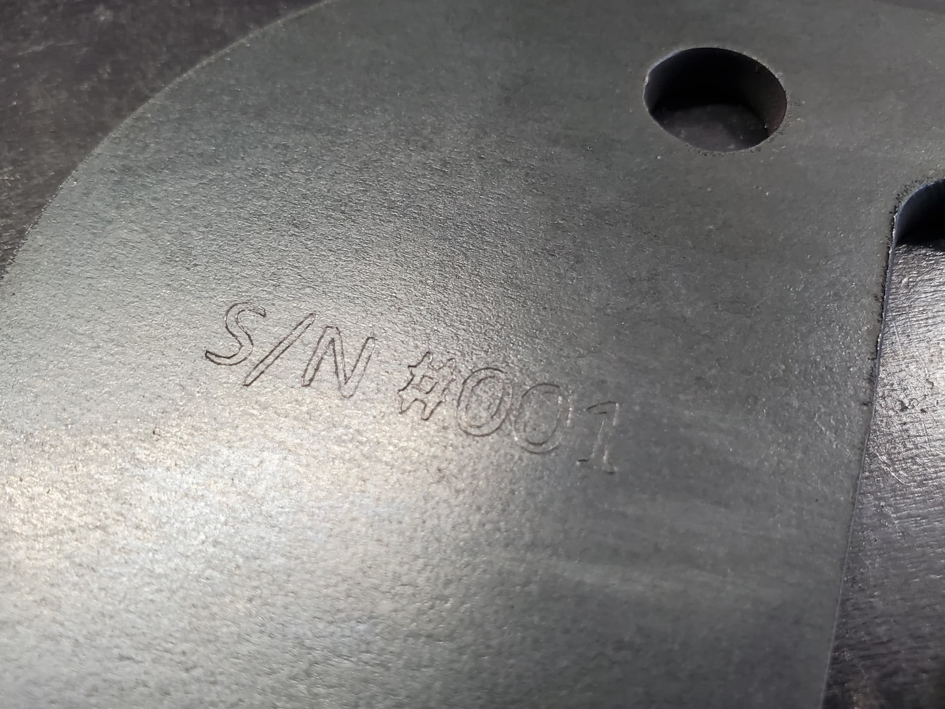
Also, unless the font is supposed to look that way…the Z axis might be loose.
But nothing needs to be adjusted for pierce delay, plunge rate, etc. Pierce delay is basically 0.
But no that shouldn’t be it, because the “hatch” lines would just fall in to be smaller than the actual geometry it’s supposed to fill if you did have any kerf width entered.
You’re avoiding a question for some reason - does the font you scribed match your design? If it does not, your Z axis assembly isn’t tight then.
With IHS you have two springs setting the sensing height, the spring of the scriber (what amount of travel is that???) and the IHS, which uses the weight of the gantry pushing down the probe. If you compensate for the scriber travel, then IHS ‘could’ work, but only if the scriber is fully seated BEFORE the IHS contacts open.
I don’t have an ‘Easyscriber’ and I don’t use my Plasma Cutter table for scribing. I have a different spring loaded scriber that must have a weaker spring than the Easyscriber. My scriber tip would be completely compressed with Crossfire system.