Haha well obviously I’m not trying to extend the X-axis, 2’ is the longest cantilever I would want without a THC. Feel free to private message or email me (ntkfabworks@gmail.com) the lead screw and lead screw nut part numbers, keep your thread clean and organized 

I would like to know as well when you are complete and tested the build. Very cool.
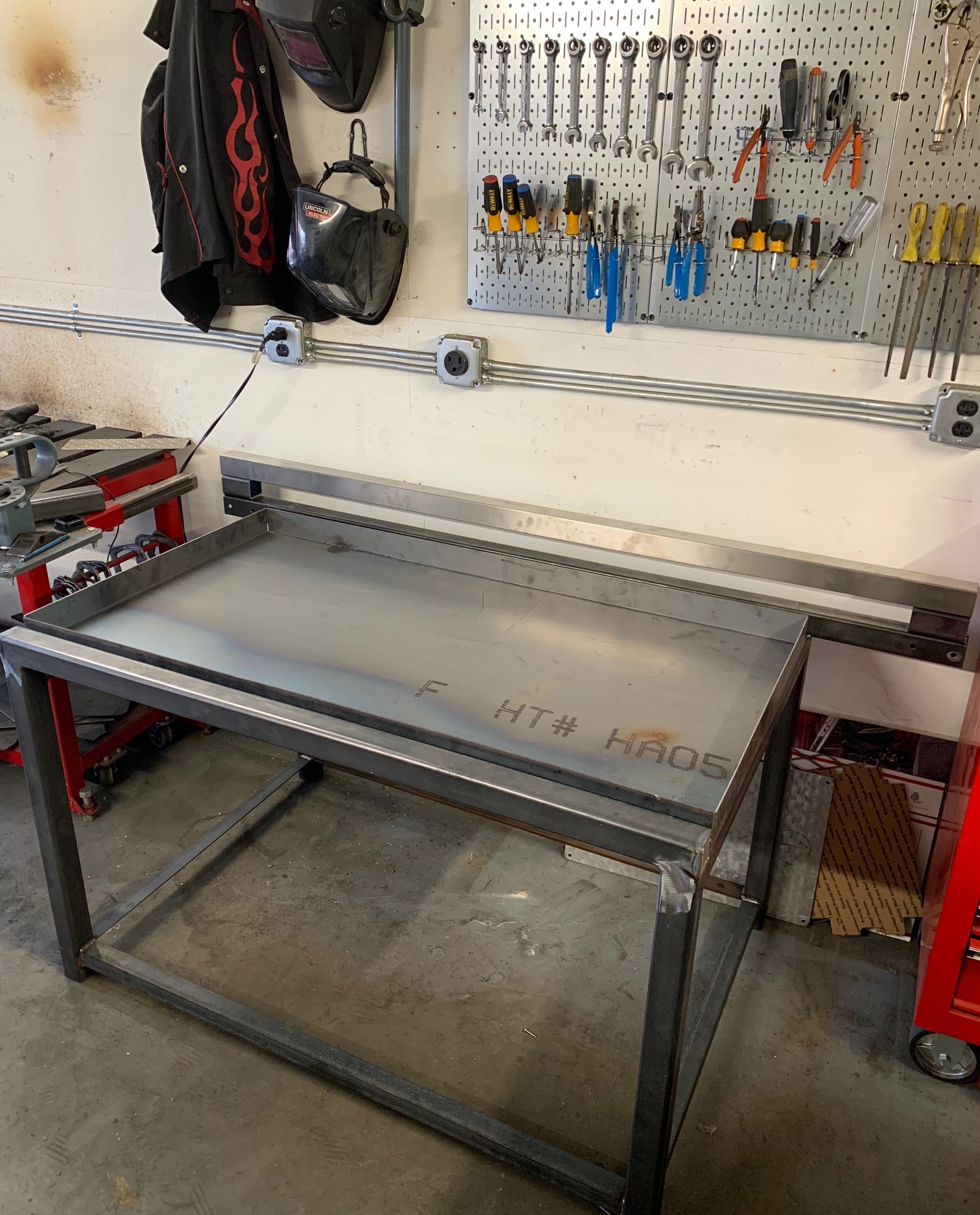
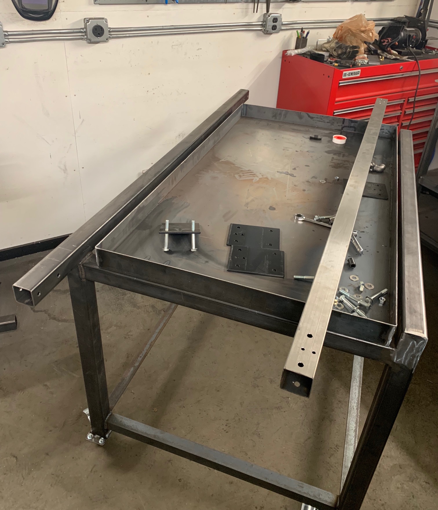
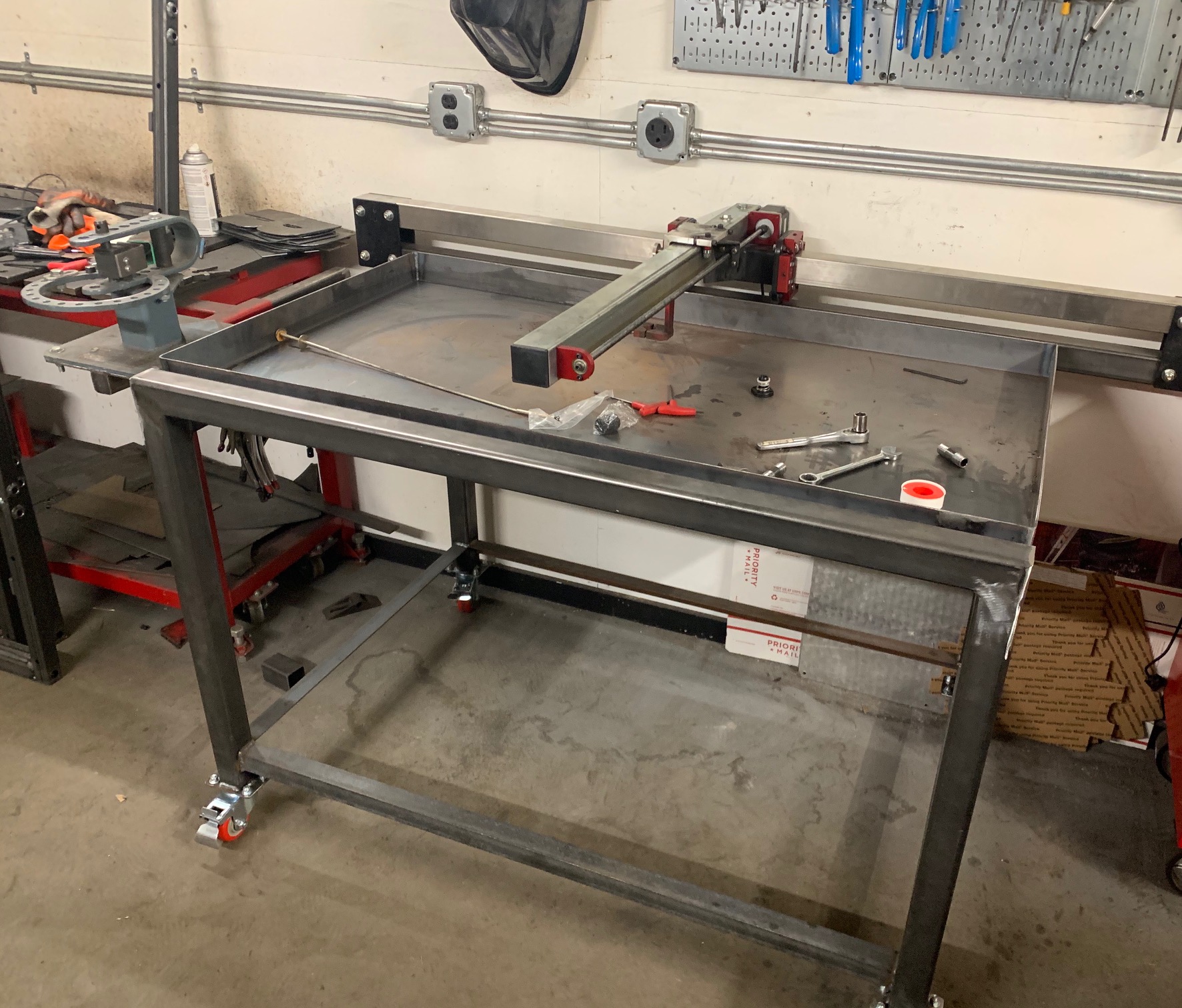
Picked up the water table today. I still have to TIG the seams but it came out great.
Picked up a piece of 3/16 for the electronics mount as well.
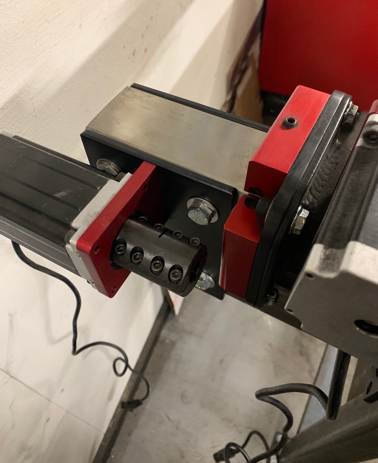
As far as the lead screw goes it’s a 1/2-10 5 start. It cost $68 shipped on eBay. It will have to be cut down around 10”. It has the same travel as the stock lead screw so nothing will have to change in the program.
The challenge is that you need an adapter for the motor and the bearing side. I am working on making the bearing side and the motor side i purchased for $26 shipped from buildyourcnc.com
Tomorrow i will weld up the water table, finish grinding work on the frame and hopefully get the casters on.
6 Likes
Looking good! Keep the pictures coming! Can’t wait to see it run! Please upload a video as soon as it gets going!
When I get some more time I will expand mine. I have my new upper and lower gantry tubes cut to size but not drilled yet. I have all the other parts on hand. Free time is an elusive creature.
1 Like
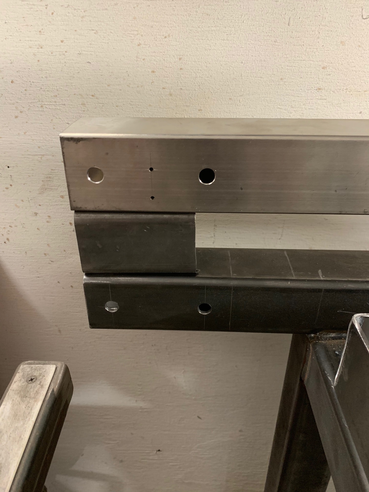
I haven’t drilled the stainless upper rail yet. Not for any particular reason.
I am not sure what my plan for the cable hanger is yet either. I think I want to design something better than the current one and it will definitely need to be longer.
Ideally the new arm will actually hold the cable in a channel rather than how it currently functioms
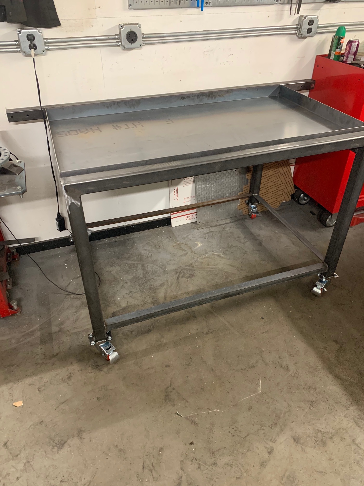
Casters are on. 4 pack from amazon $24.
The adapter for the motor end came today, it’s acfually gigantic not sure if it will even fit on the crossfire I’ll have to check tomorrow.
My machine is cutting like shit now because the slat holders are all messed up and sit at different heights. They really need to improve that design.
2 Likes
I may have missed it, but Will you still be using sheet metal screws with the rubber washer to fix it to the frame of some type of clamp or weld on to the frame?
I actually just finished it.
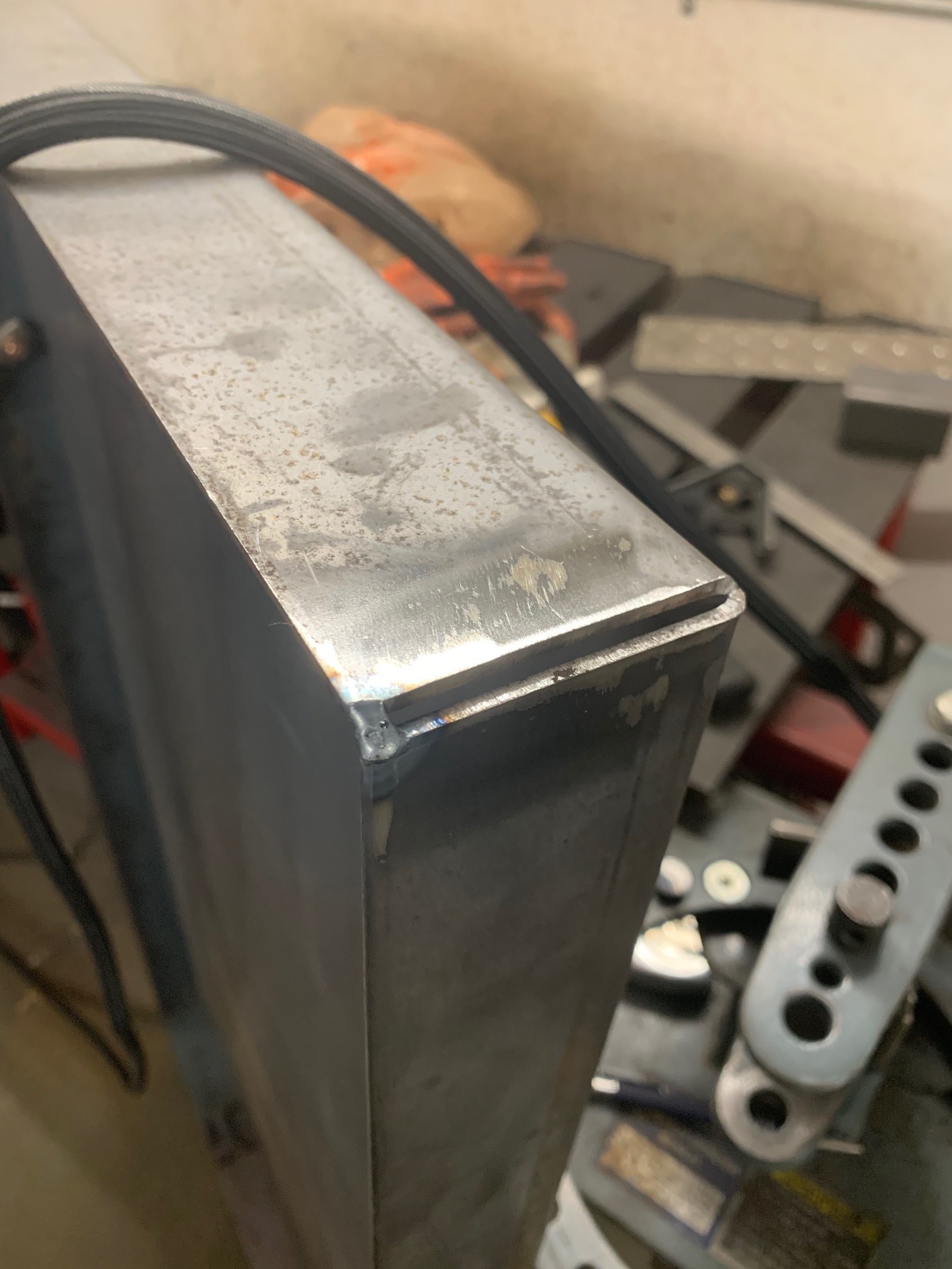
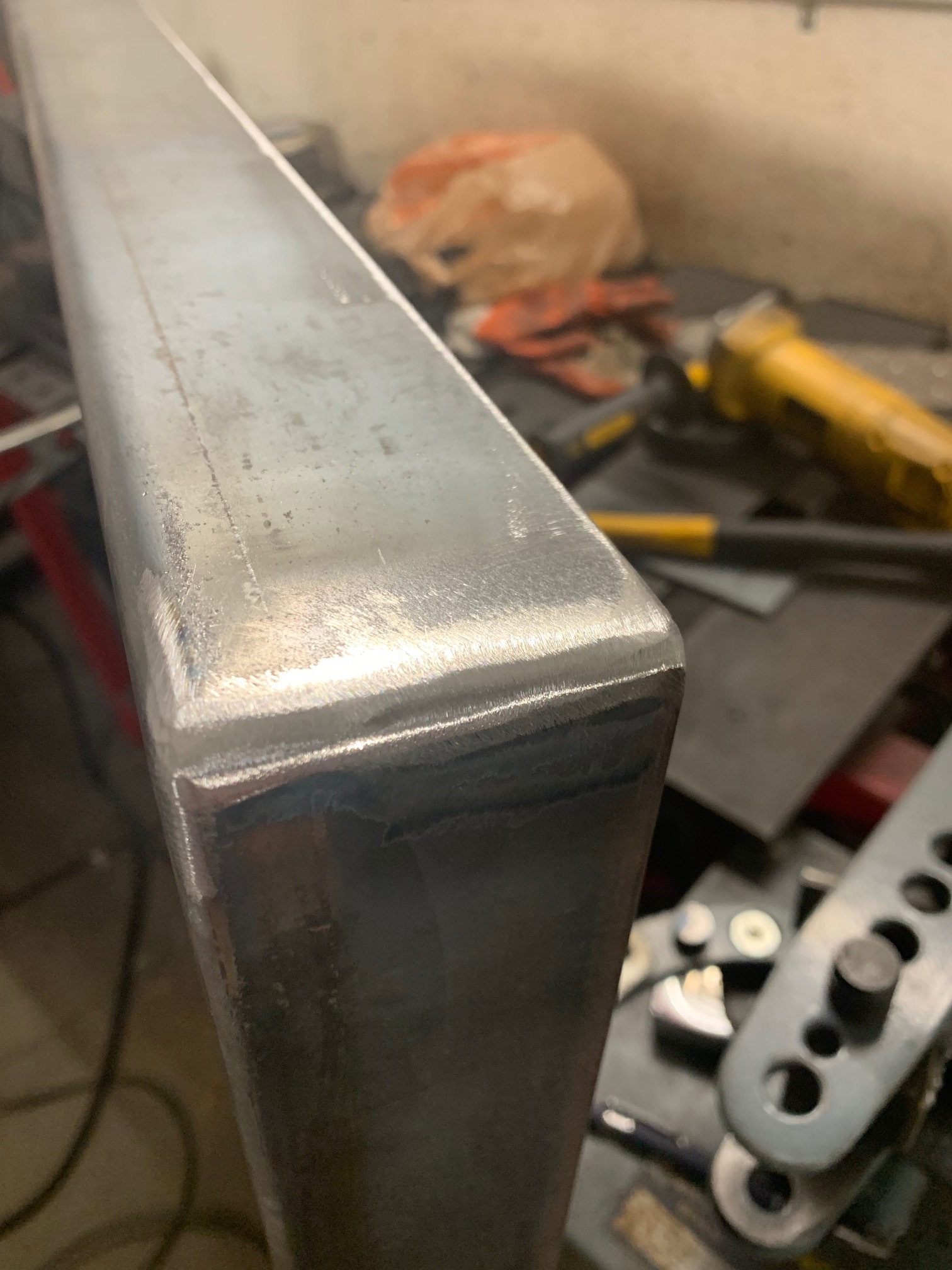
First I proceeded to weld up and grind down the corners of the bent tray. I TIG welded it to ensure full penetration. I would have left it but I am not the world’s best TIG welder so I opted to grind it down so no one will ever know…
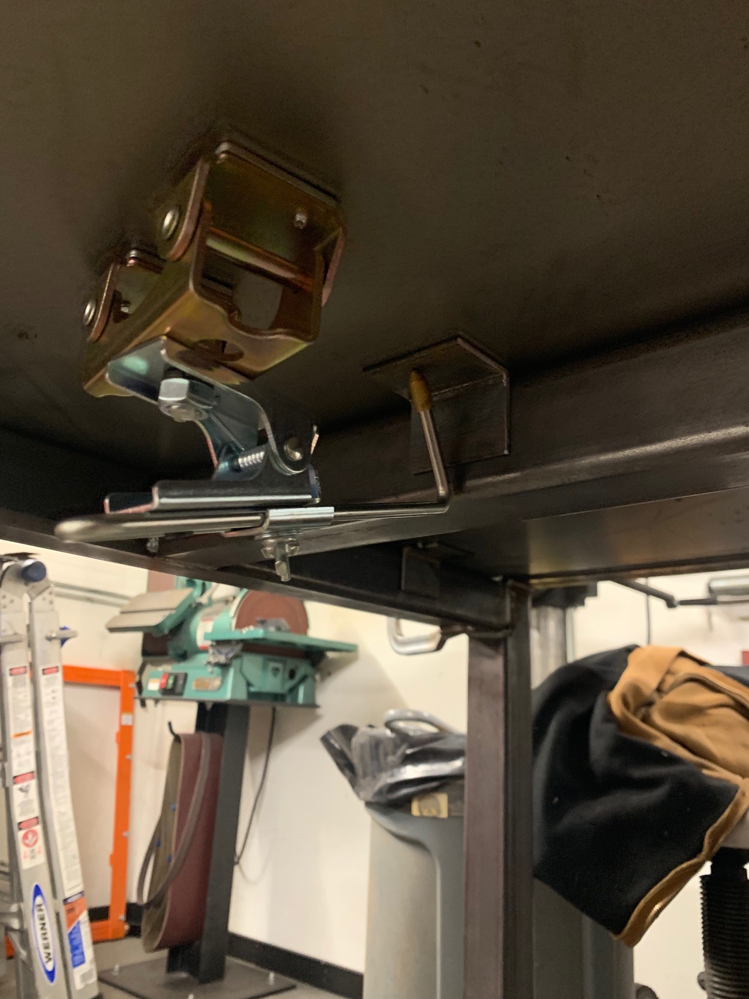
Next I moved on to the mounts. I guess you could call it more of a clamp. In the photos below you’ll see I utilized eight 2" long 1.5x1.5" angle iron cut offs to lock the water table in place on the frame. Other than the drain it isn’t a great idea to drill through it. I was really worried it wouldn’t fit after welding/warping but everything worked out well.
The water table is very firmly locked in place with this design and once it has 80 lbs of water in it, it really won’t budge.
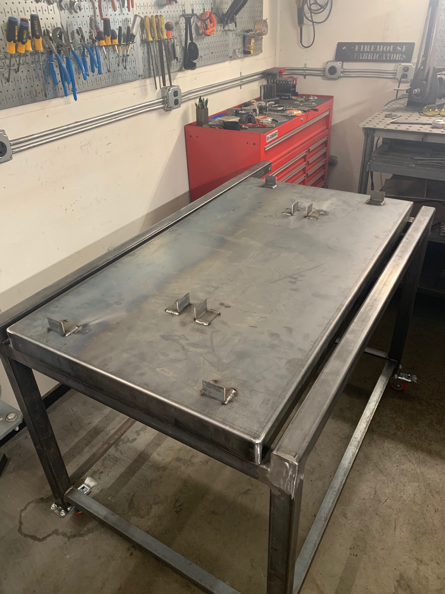
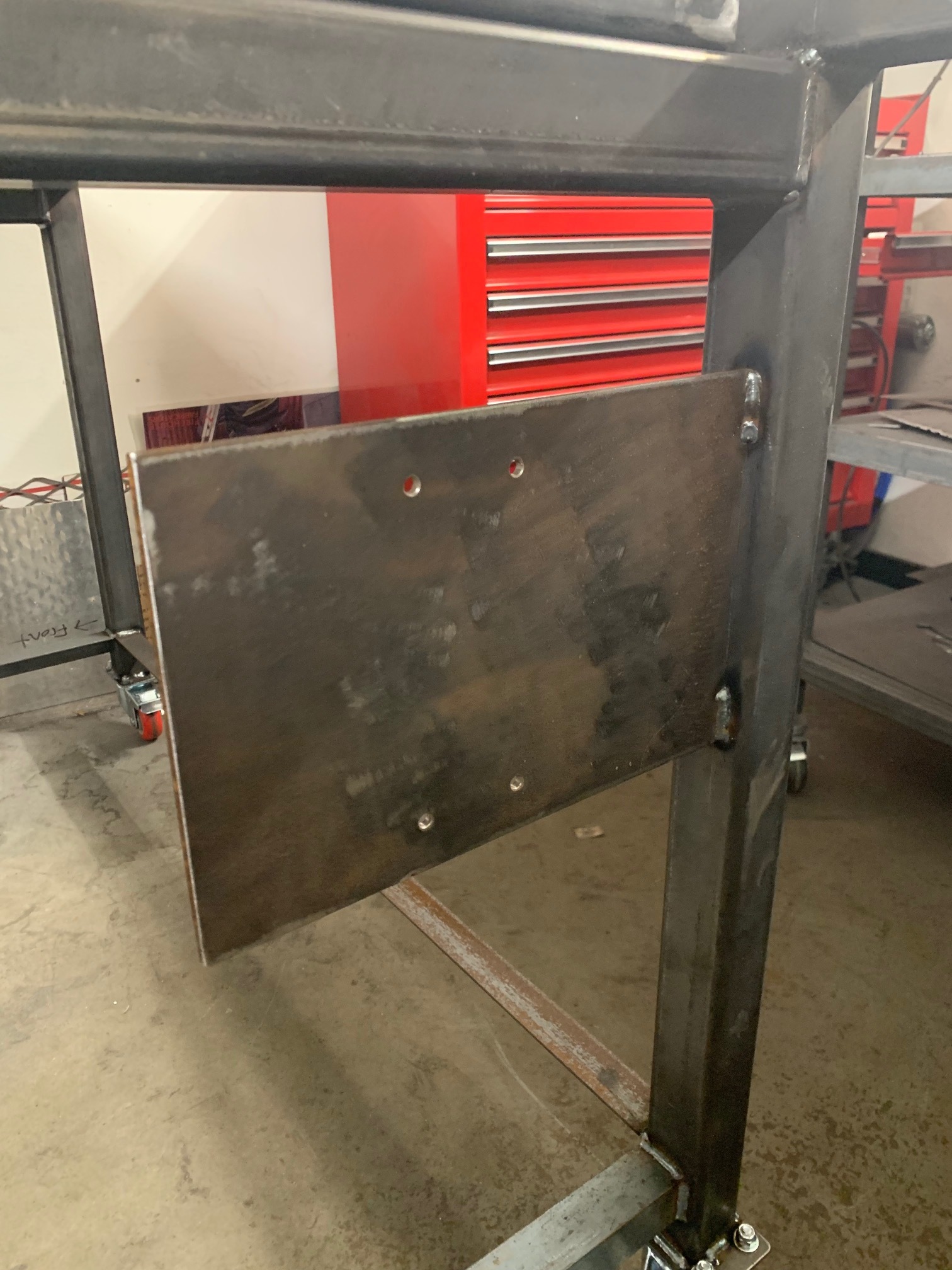
Lastly for the day I made the plate for the electronics enclosure to attach to and welded that in place.
The leadscrew did arrive however they’re out of stock on the 4 bolt style flange 1/2-10 5 start nut. I am waiting for it to return to their inventory to order it.
Next on the list I suppose is adding slat holders to the water table and determining where I will put the drain. I would like to install some form of pump and water holding tank as well if I am doing all this it seems silly not to have one.
3 Likes
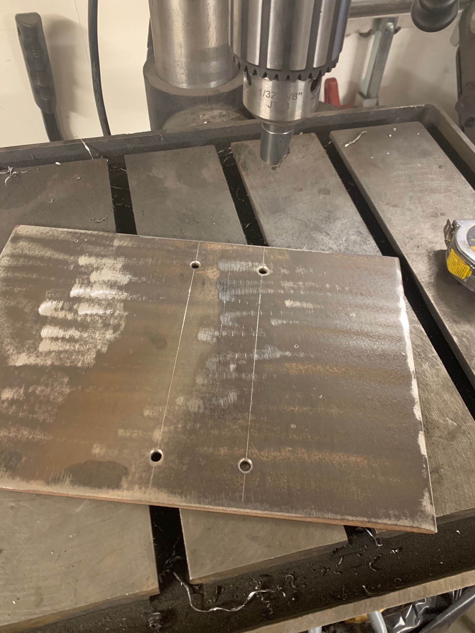
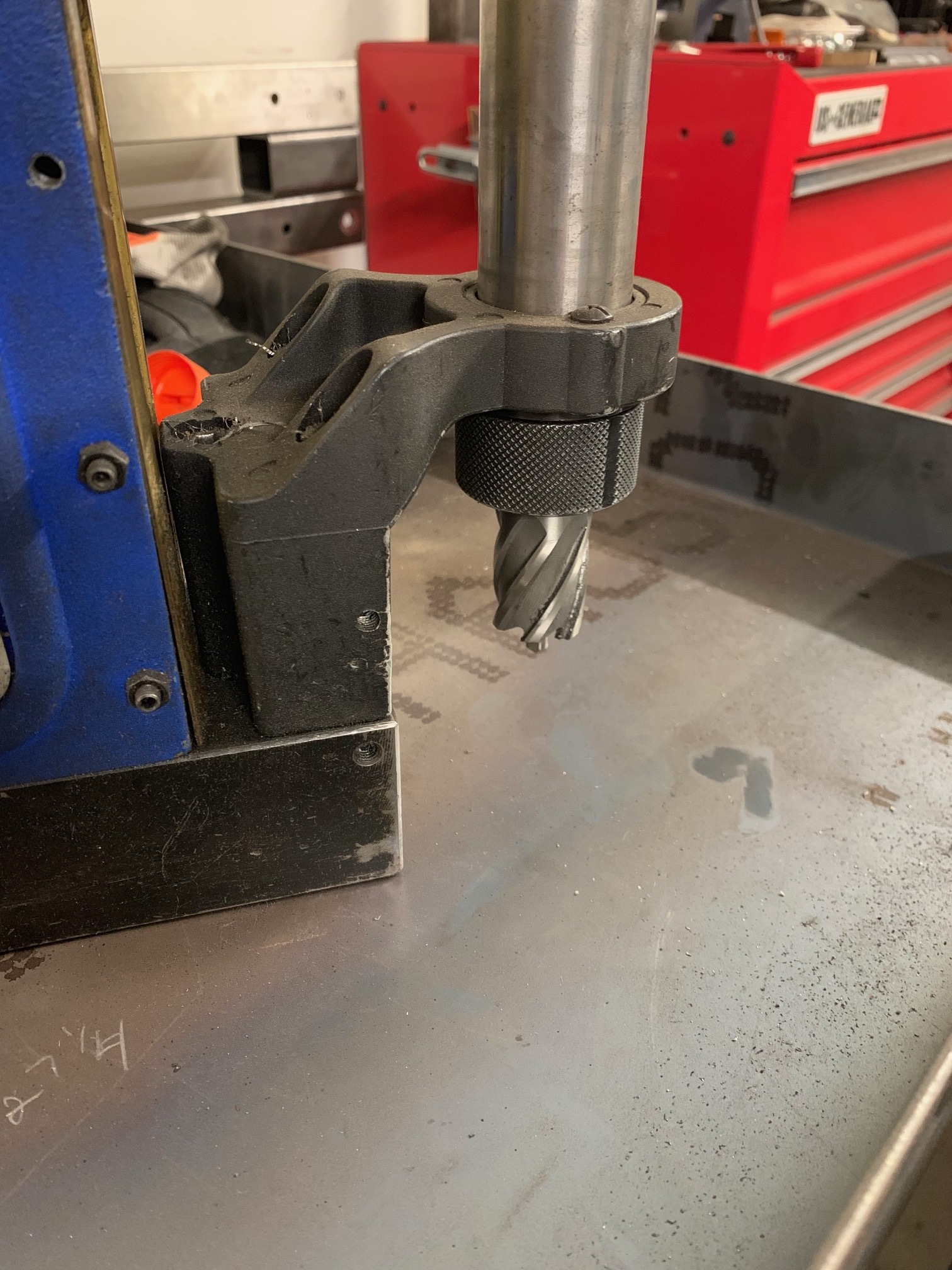
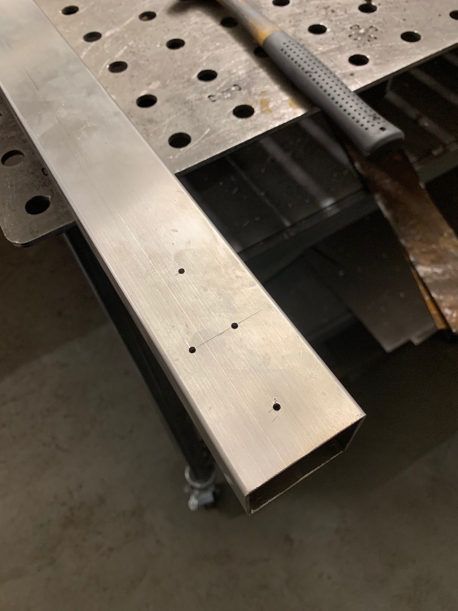
Nothing crazy today just drilled out the stainless finally and started getting ready to drill some holes in the water table for a drain.
I think I am going to use the front corner. I hate trying to get all the water to train in the center.
2 Likes
Final update for the next few days. Have to go to actual work unfortunately.
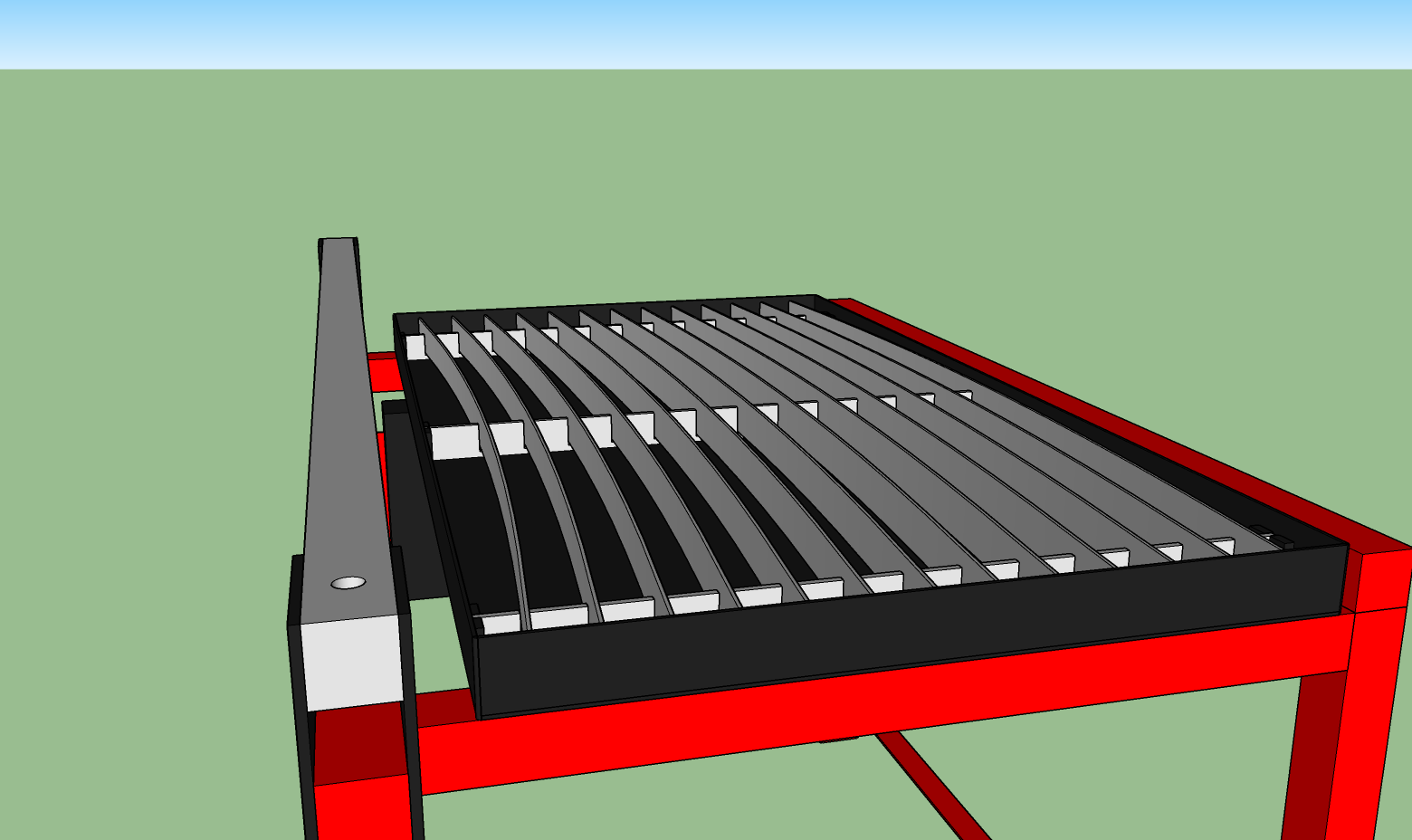
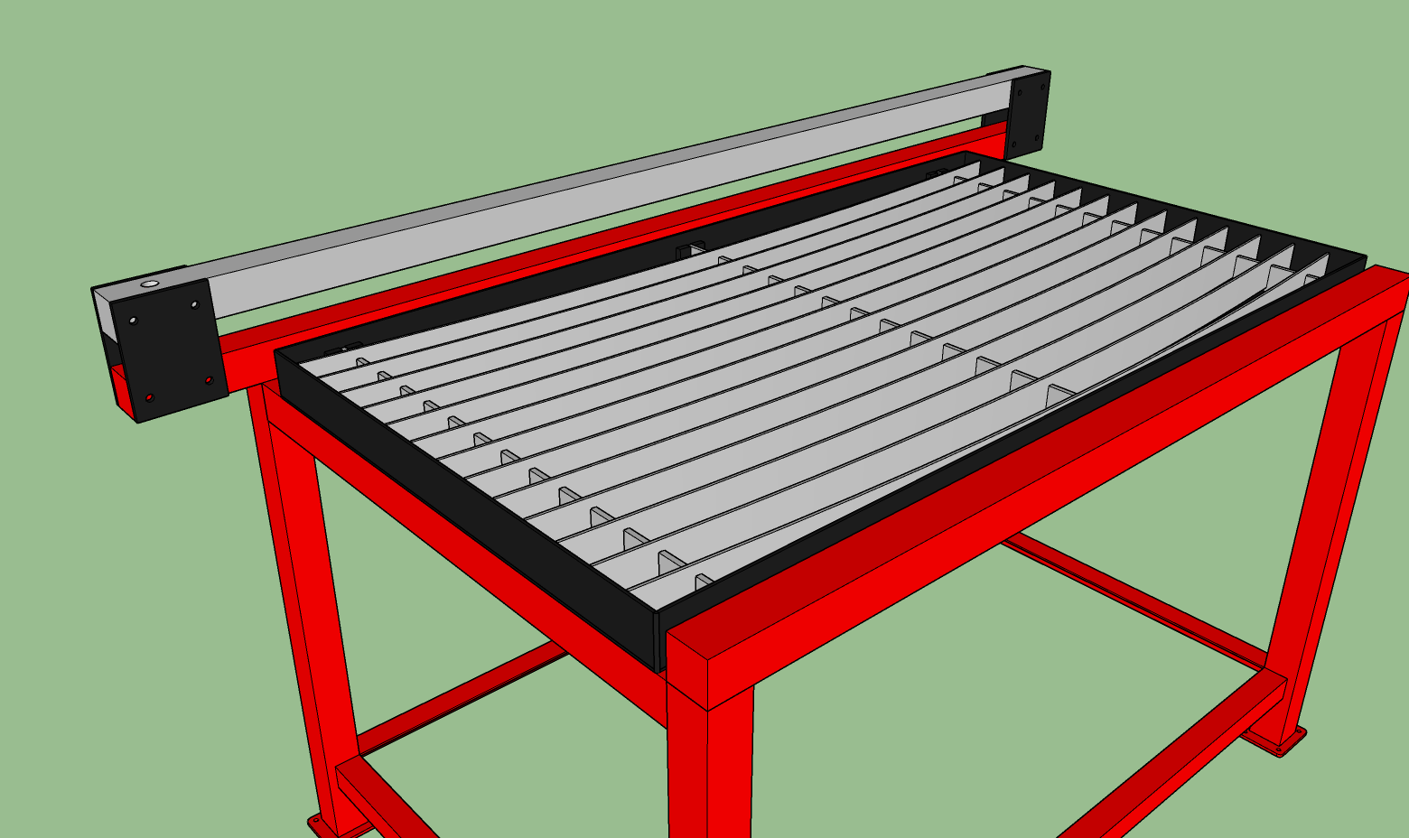
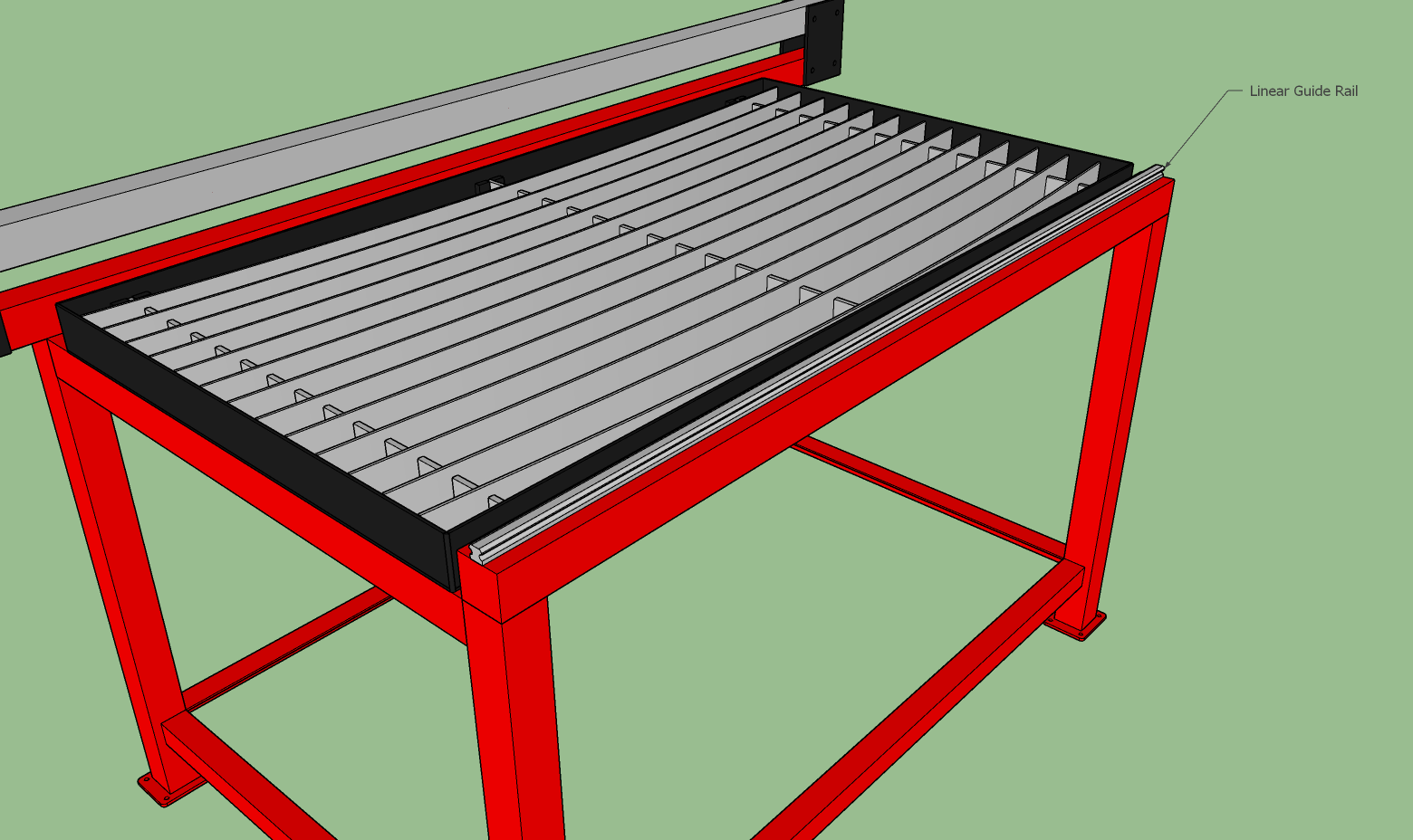
Finished drawing the slat bed and holders. Hopefully this design will work. The slats have a 1" bend to them at the center. 2" tall slats. The actual slat holders are secured loosely between a couple of 3/8" blocks welded in place. Hopefully the bend in the slats is enough to keep them locked in place.

3 Likes
cant wait to see the water table
Project looks great!! This will definitely open up the window of projects.
Another tiny update
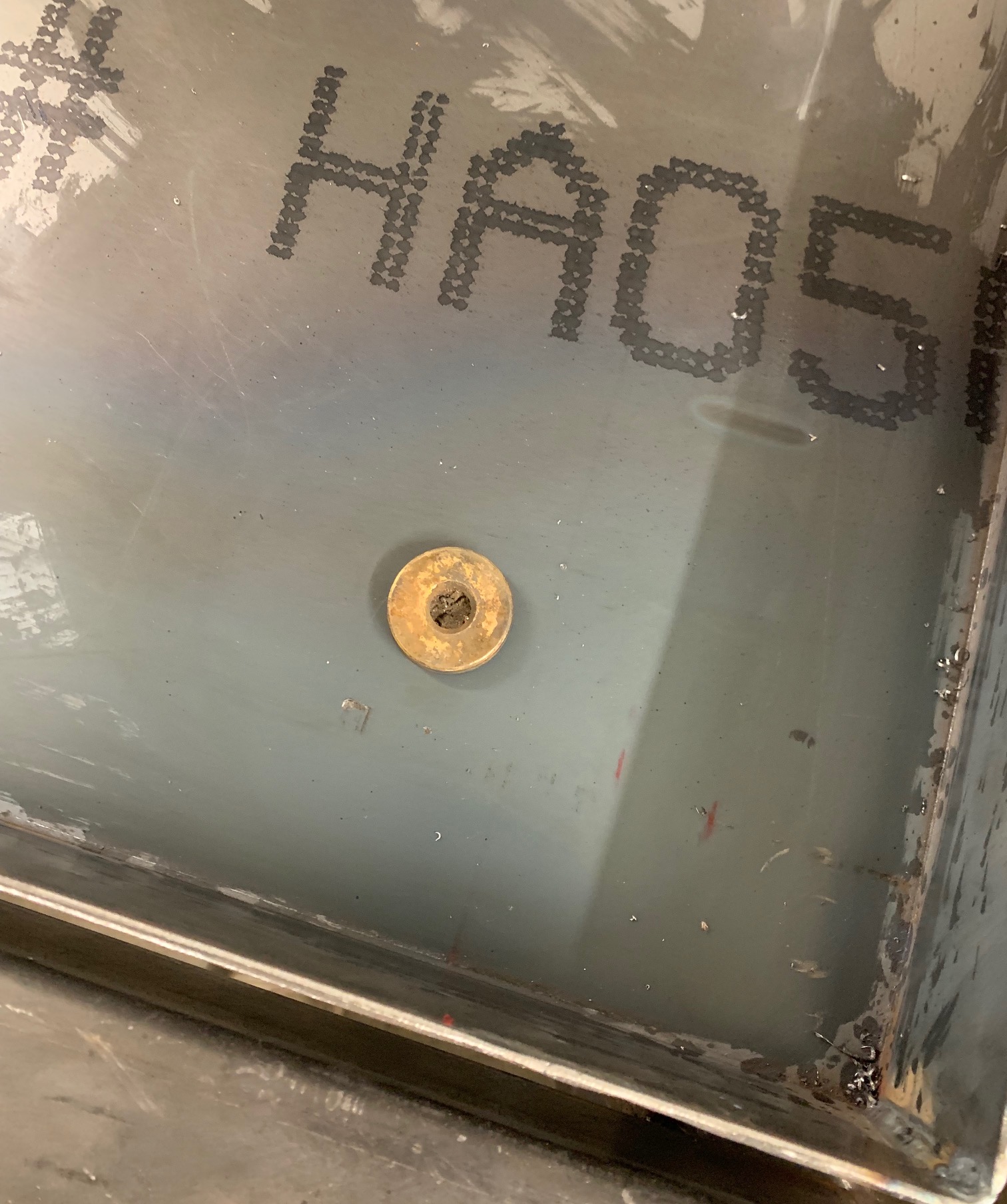
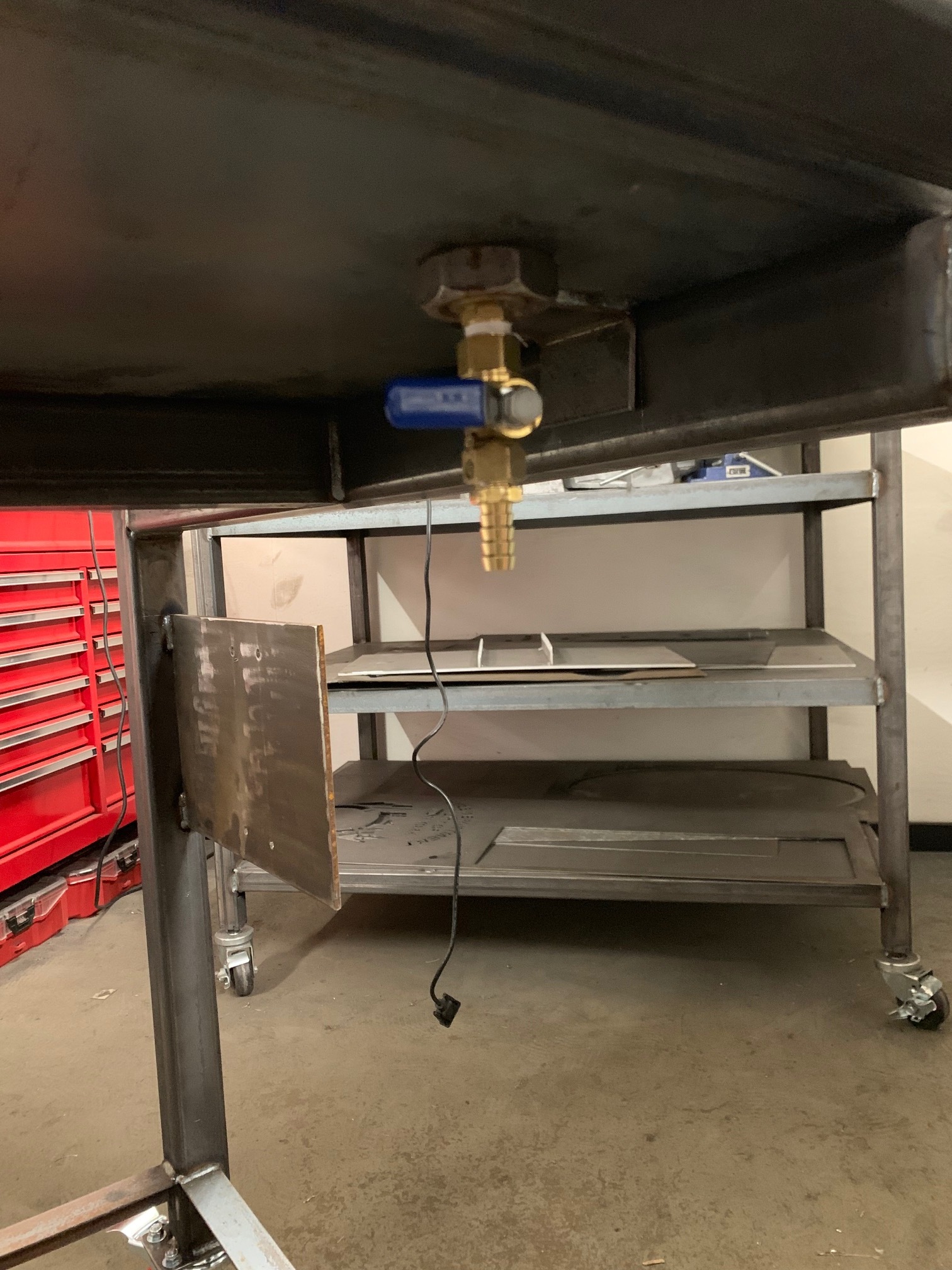
Drilled a 1” hole in the water table for the drain plug. I’m reusing the drain from the crossfire but i won’t be using the anode it doesn’t seem necessary.
Will he piping a ball valve underneath in place for easier draining.
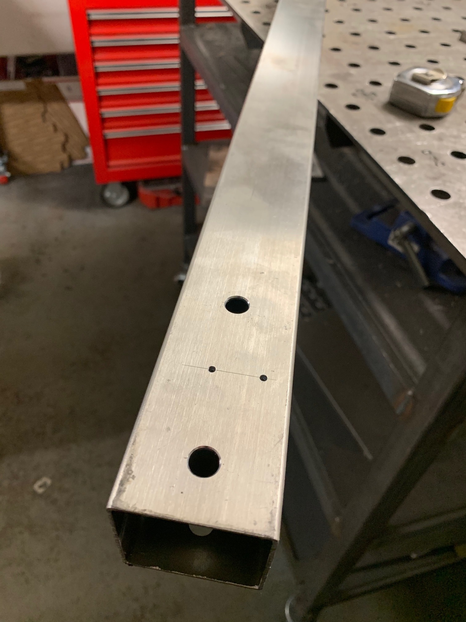
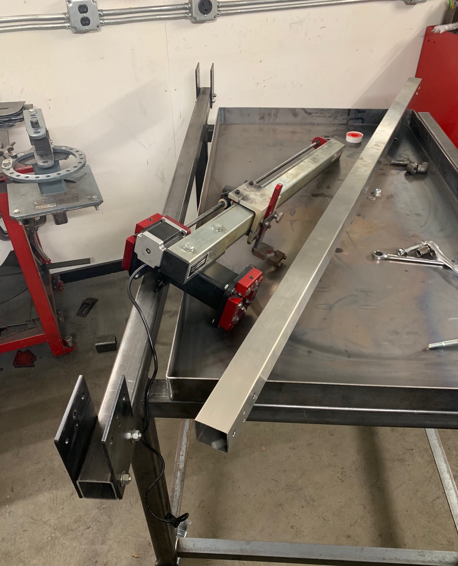
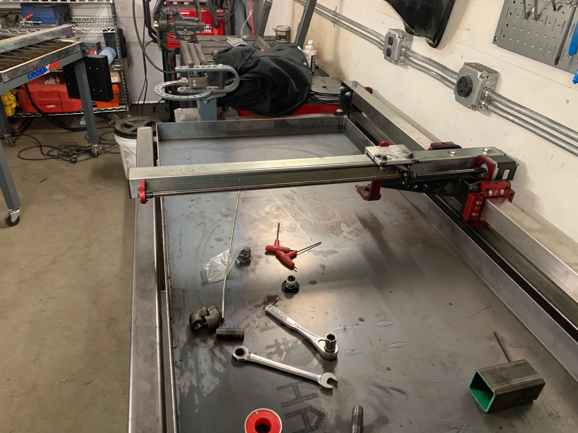
Got the upper rail drilled and gantry arm mounted.
With crude measuring using a block of 2" tube to the bottom of the water table, the gantry arm tracks within 1/16" from right to left. It touches the tube at the right side and at most 1/16" drop to the left. If I had to guess this is more the result of using a drill press and measuring by hand rather than the actual table itself. I was fairly spot on with the holes for the bolts but human error and whatnot always prevail. I can probably correct this by drilling the holes of the upper rail oversize giving me some play to match it to the water table but I am going to wait until it actually has slats and I can properly measure how it tracks rather than guestimate now. Regardless it is already more precise than the stock crossfire on its flimsy frame anyhow.
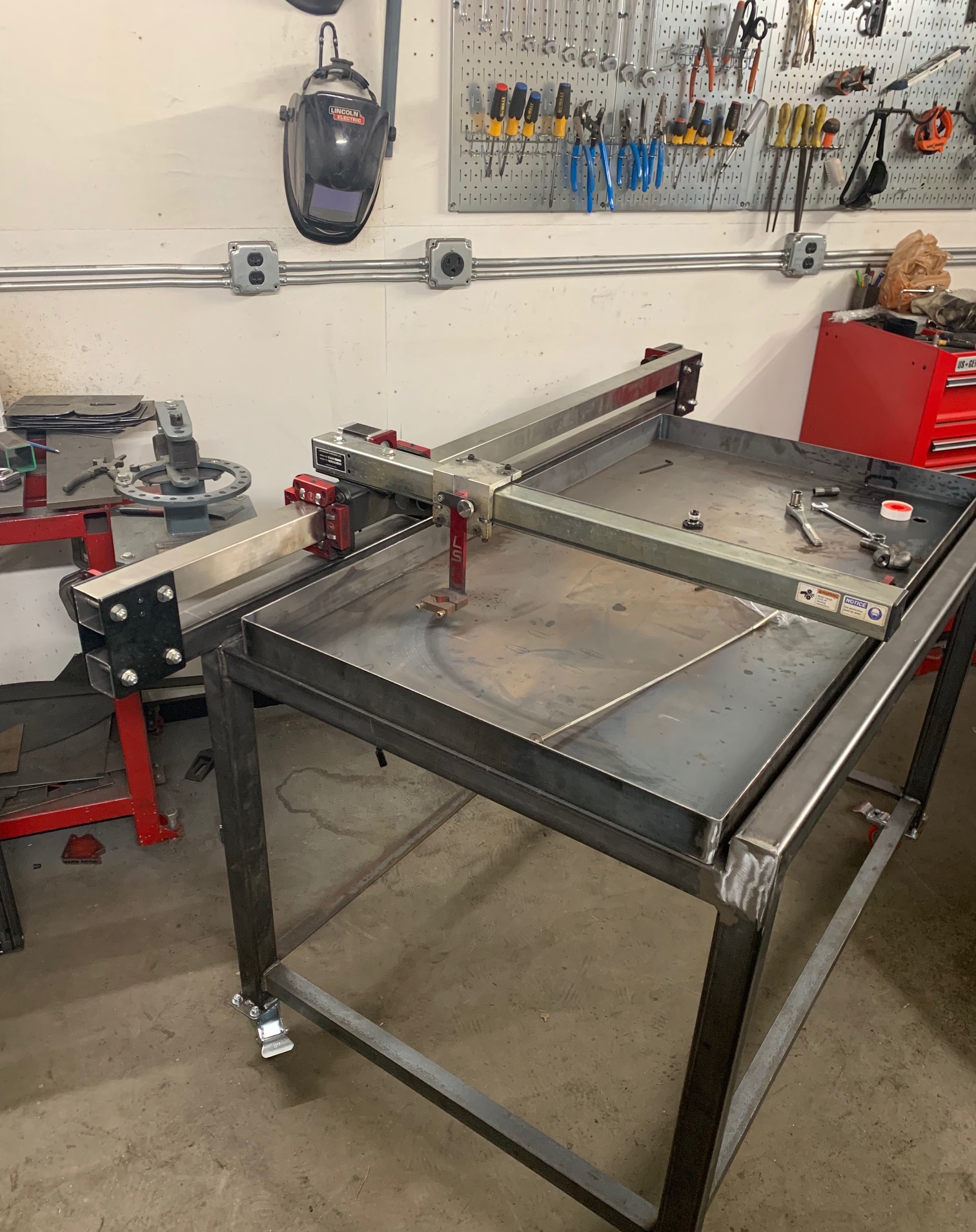
I hope to have the Y axis moving around tonight. The X axis will have to wait because I need wire and connectors to extend the wire on the motor.
In the photos you can see the gantry arm does reach just over the edge of the front of the table itself where it should allow me to at a later date add a bridge/track for some kind of bearing mount to attach to the bottom of the gantry arm and give it support for the weight of a Z axis. This is out of my wheelhouse at this time, I am taking it one piece at a time.
Still to be determined is the torch hose support arm. It will need to be bigger and taller than the stock arm to allow for the increased travel. I Am not sure if I want to mount it how the original arm is mounted or put it on some form of bearing assembly for smoother rotation.
4 Likes
Its looking reaaaallly good!
Looking really good!
More updates. Added the ball valve for the train. Again I will not be using the anode, it seems pointless. I was going to add a holding tank but it also seems like a pointless waste of money when I can just use 5 gallon buckets with a screw top and dump the water back in.
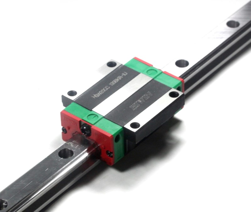
I will also be adding some form of guide/support to the opposite end of the gantry arm for future addition of a Z axis. (I believe it will be necessary for the aprox 5-6 lbs added by a z axis)
At the suggestion of Gamble Garage I am going to use a linear guide rail and carriage. I am not sure yet how I will attach it to the gantry arm but I have some ideas in my head. As an after thought, In order to align with the table I have designed it will have to be offset to the left side by 2" so it does not run off the front and I won’t have to extend the table frame. I was a little concerned about the off set but the weight is so minimal and the offset is relatively small as well it shouldn’t be a big factor.
3 Likes
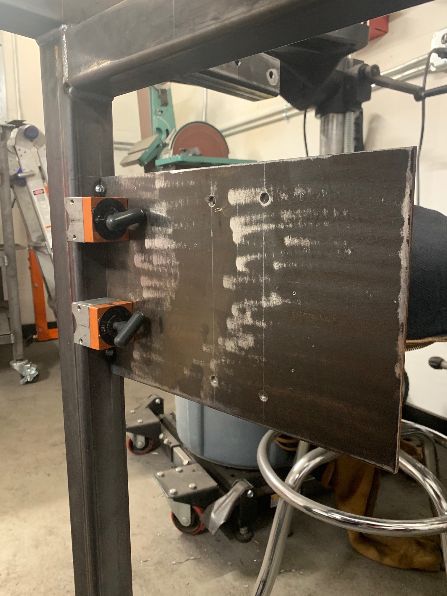
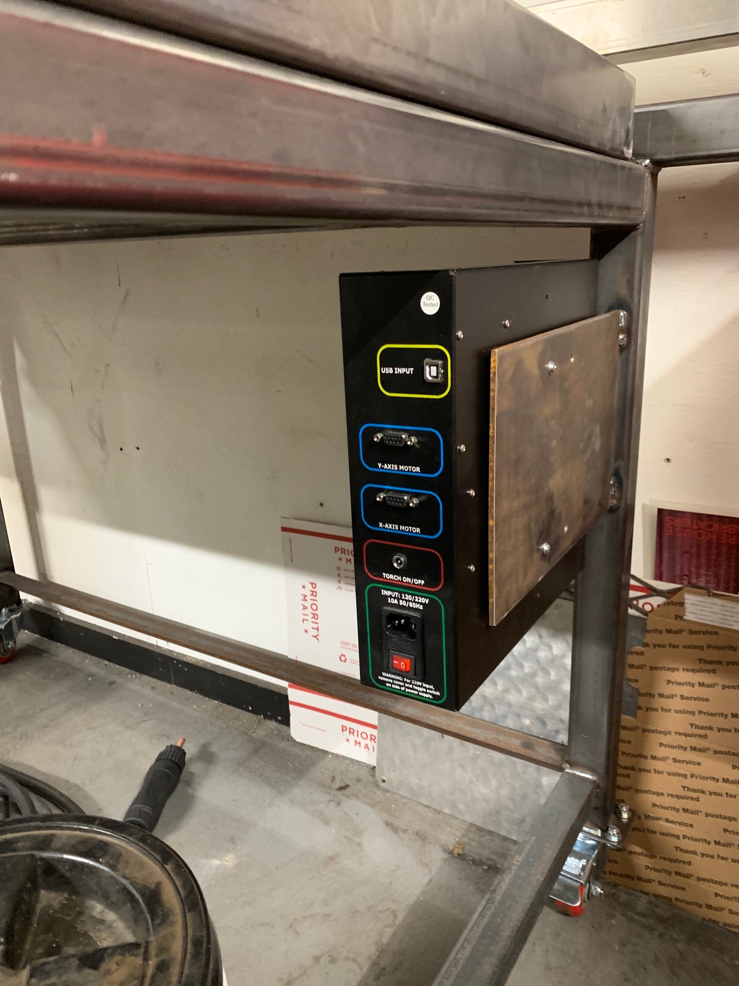
Started working on the electronics today. I screwed up with the mounting holes on the table itself I may weld them and smooth it out because it will bother me to have 2 unused holes…
I need to find 22awg 4 conductor wire to make extensions for the motors.
I am going to reverse the X and Y motors as well so that the long span is the X.
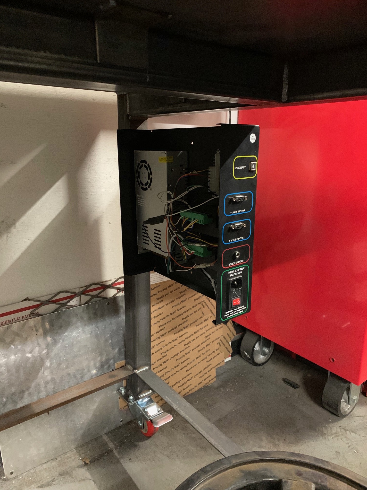
2 Likes
Looking good so far. Very interested in the total cost for you as well as any troubles you found along the way. FANTASTIC
Without incorporating any kind of support for the gantry arm or the lower shelf of the table, its $500 roughly.
If I add a support for the gantry arm and Z axis we’ll be closer to $1000.