I’m new to the forum and wanted to share some assembly tips that I have used to assemble my (new to me)/used Crossfire XR. First a little introduction is in order, I’m not new to the CNC/NC world, I came from a machinist back ground many moons ago. I currently have a 4’x8’ CNC router and a 150w CO2 Laser as well. The CNC router I designed and built and you can see a build log over at CNCZone: CNC Router Build.
I acquired my Crossfire XR late summer of last year as a “used” machine and I use the term used lightly as the machine was assembled up to about step 3 and one limit switch in step 4. I was told that it basically sat in a barn for 2+ (probably longer) years untouched, you will notice some lightly rusted areas due to the high humidity environment it was sitting, very minimal to be honest. All the remaining parts were still in plastic and/or sealed boxes. So I loaded the frame on my trailer and and parts in the truck back home in my unfinished shop as I recently built a “barndominium” or “shouse”, whatever you want to call it. And I promised to my wife I wouldn’t build the shop until the house portion was completed, Promise kept ![]()
I hope these tips will help others in there build and/or troubleshooting. I started off basically taking it almost completely apart and started from scratch and I’m at Step 10 the Water Table. I’ll start off saying I don’t have any proof of accuracy and performance of the build yet and I will update that as I progress in the assembly, so take it all with a grain of salt ![]() as your mileage may vary.
as your mileage may vary.
To align the frame I used Spud Wrenches in the Red outlined holes and hand tightened the 2 bolt locations in Green. This for me worked great and then leveled and squared up the frame.

Spud Wrenches
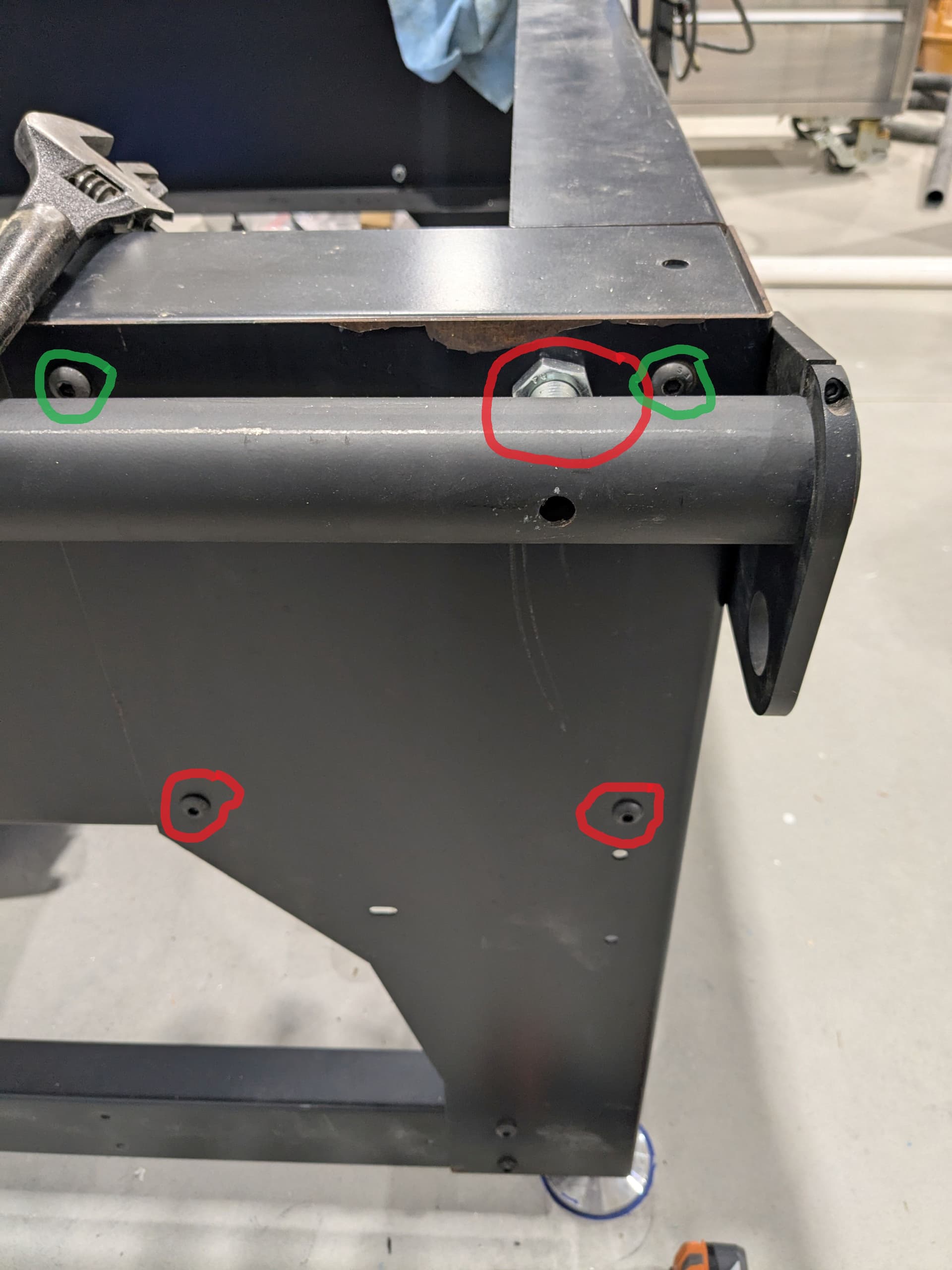
Bolt Locations

Example of some of the small holes lined up in opposite corners.
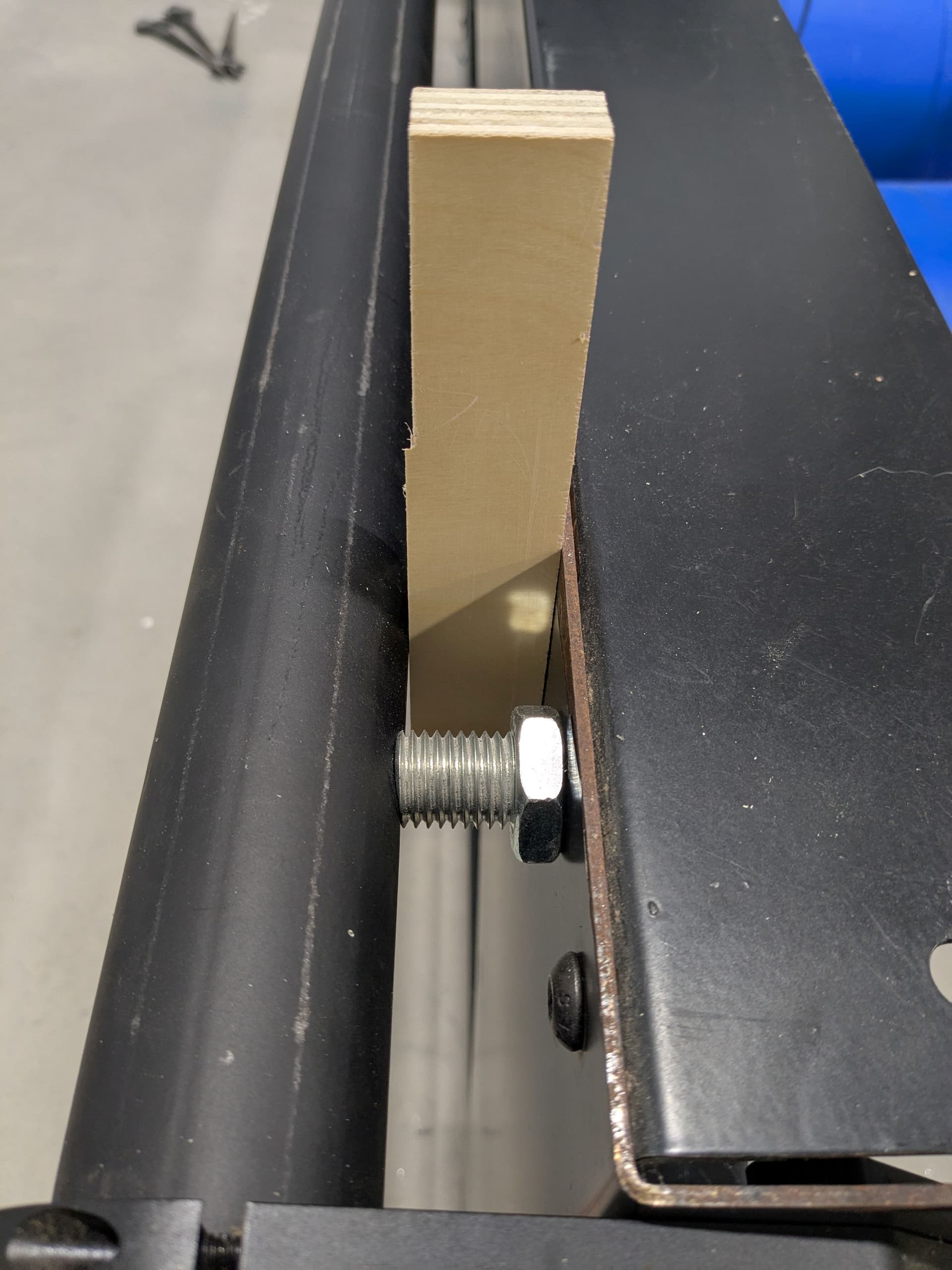
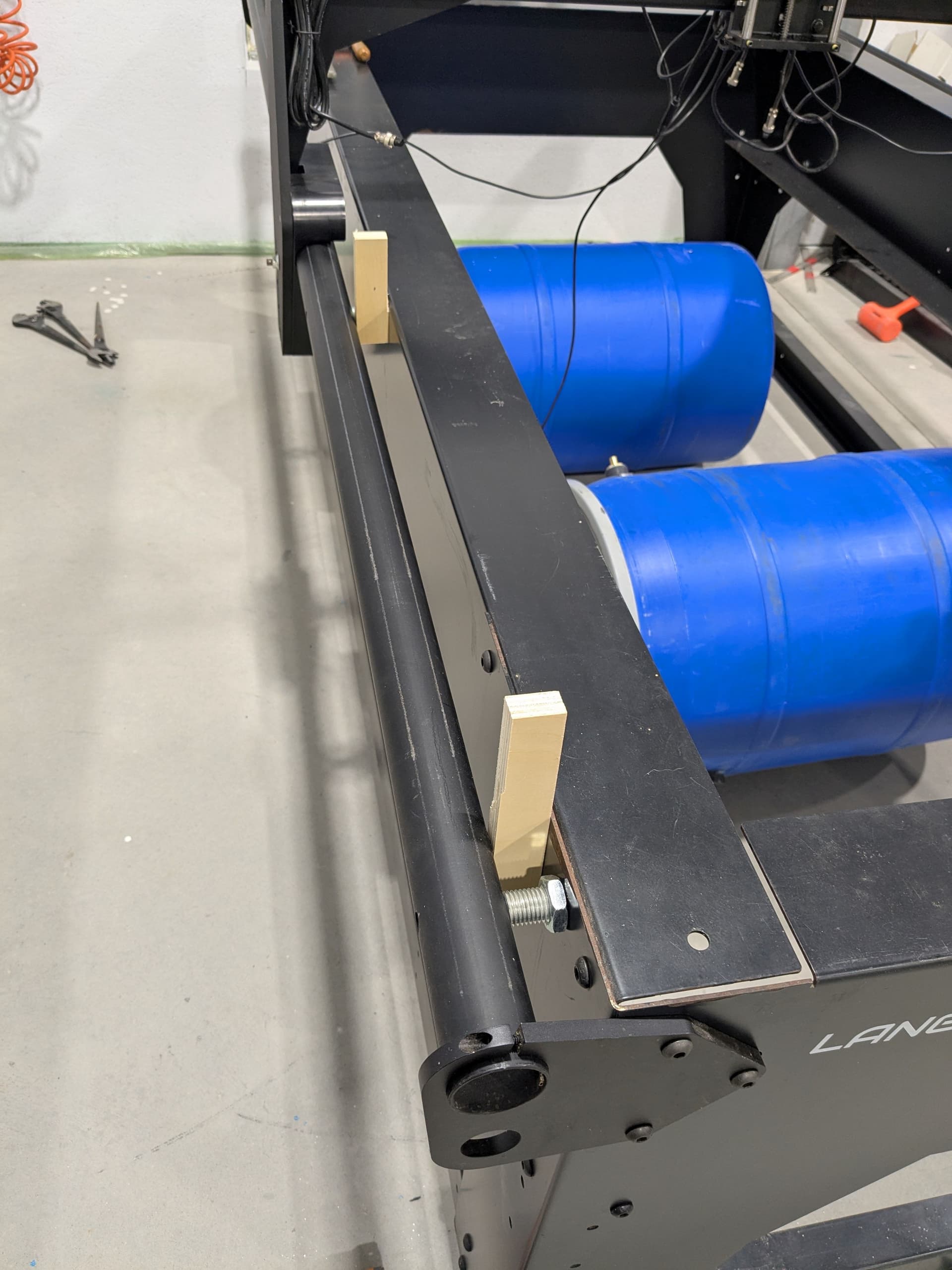
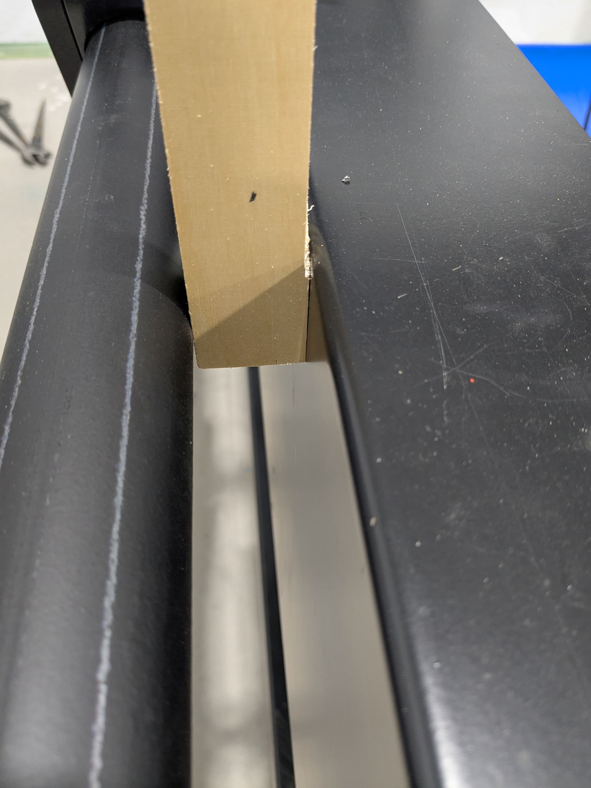
After this it was time to do the Y-Axis Rails. I used some Blue Loctite on the 1/4"-20 socket cap screws for the rial stabilizers and made sure the “fish mouth” mouth was seated correctly. I made a wood gage block for the 1.25" using dial calipers for all gage blocks. Slightly tight the 2 ends so the gage block fits, then I dialed in the height of the rail at the ends with a piece of angle iron across the entire table.

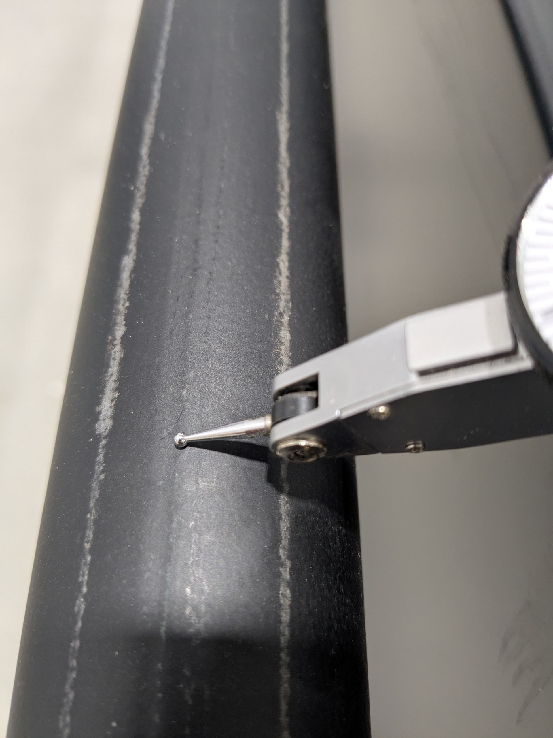
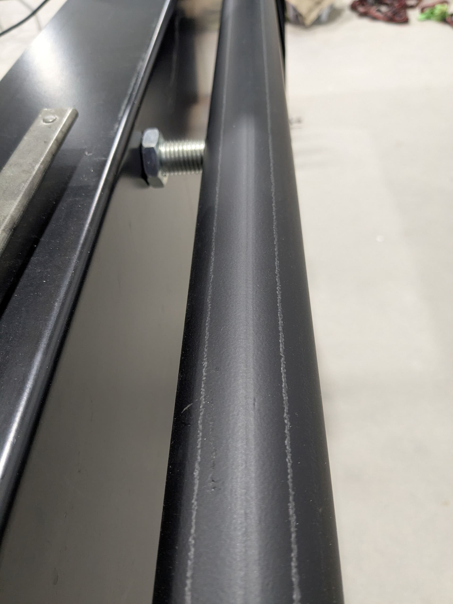
Note: these rails are seam welded tubes, one side will seam up and the other side seam down. On the seam up side note the location of the dial indicator here.
Once I had the ends dialed in of the first rail I set the other side up using the same method, I just carefully lift the angle iron over and flipped it over to the other side making sure that the height of the rail was the same.
Measuring the inside of the wheels of Gantry I found to be rather difficult by myself so I made another gage and measured it then added the 1.75".

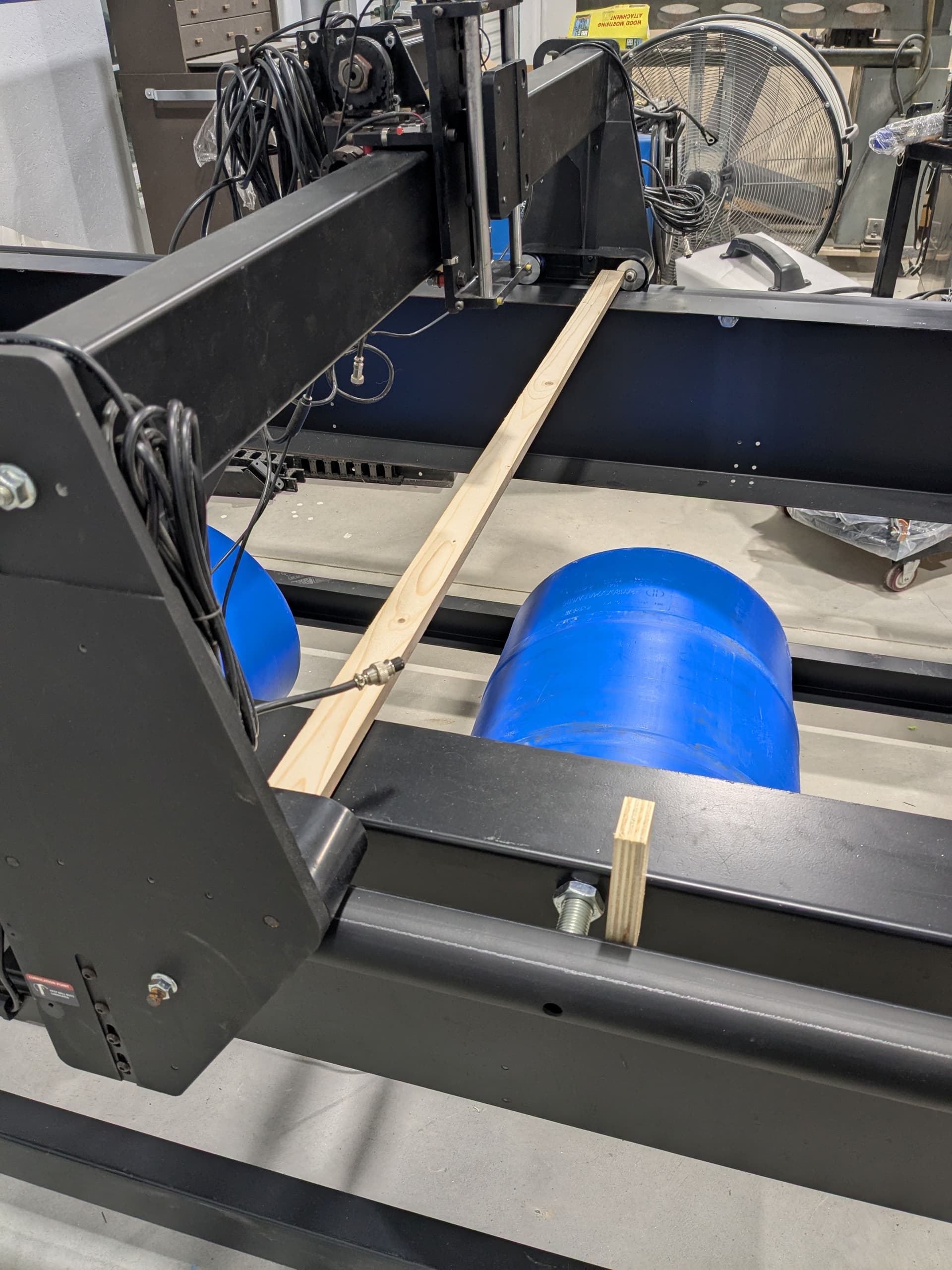
So, to set the middle 2 rail stabilizers I couldn’t just follow the directions as in my mind there is no way these tubes are straight. Made another gage for the left side adding the gage thickness of the frame to the 1.25", set the width and used the angle iron dial indicator setup to set the rail height. The gages made for the other side ended up being almost 1/32" less.
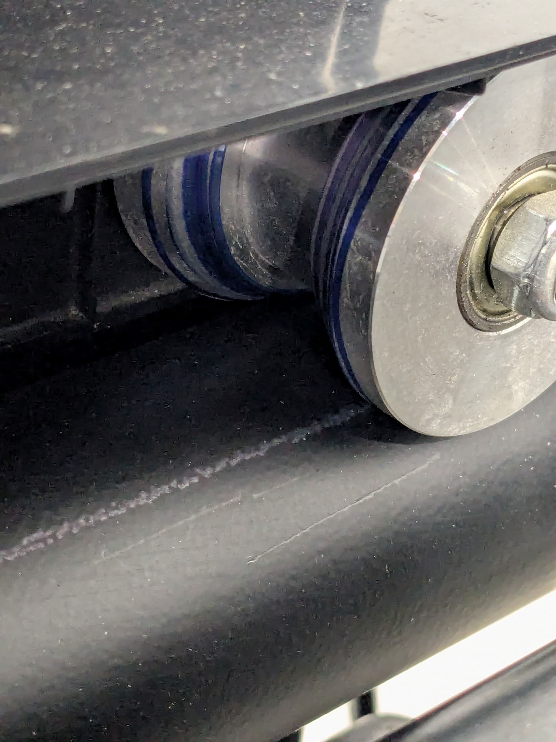
Once the Gantry was mounted I used a Blue Sharpie and painted the rollers moving the gantry back and forth so I could make sure everything was in full contact as seen here:
Checking the Gantry level acros the entire table lenght was very good:

I hope I got the order of pictures correct but if not I’ll post the ones I missed. This is a long posting and I hope this all makes sense and helpful to others as I have learned a lot thus far from everyone here on this forum. Not sure but I’d like to think some of this could be applied to building the Crossfire Pro table as well ![]()