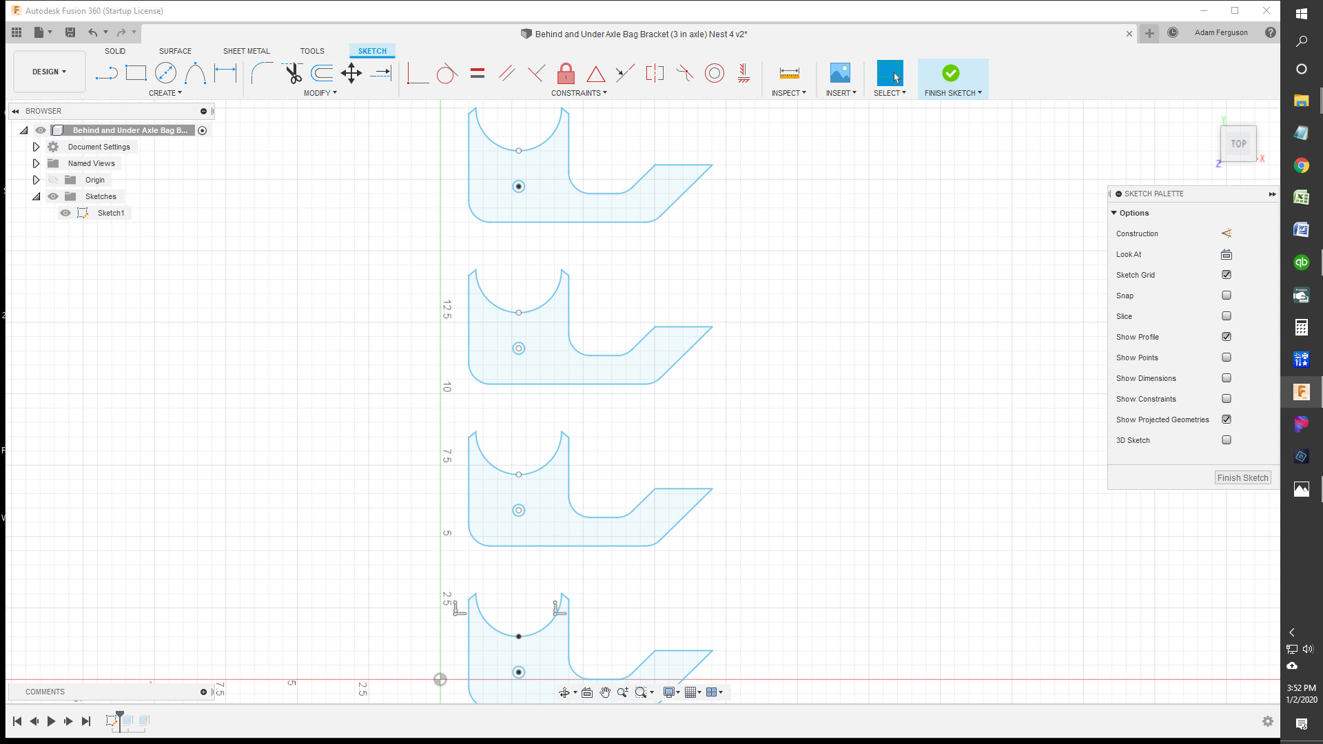
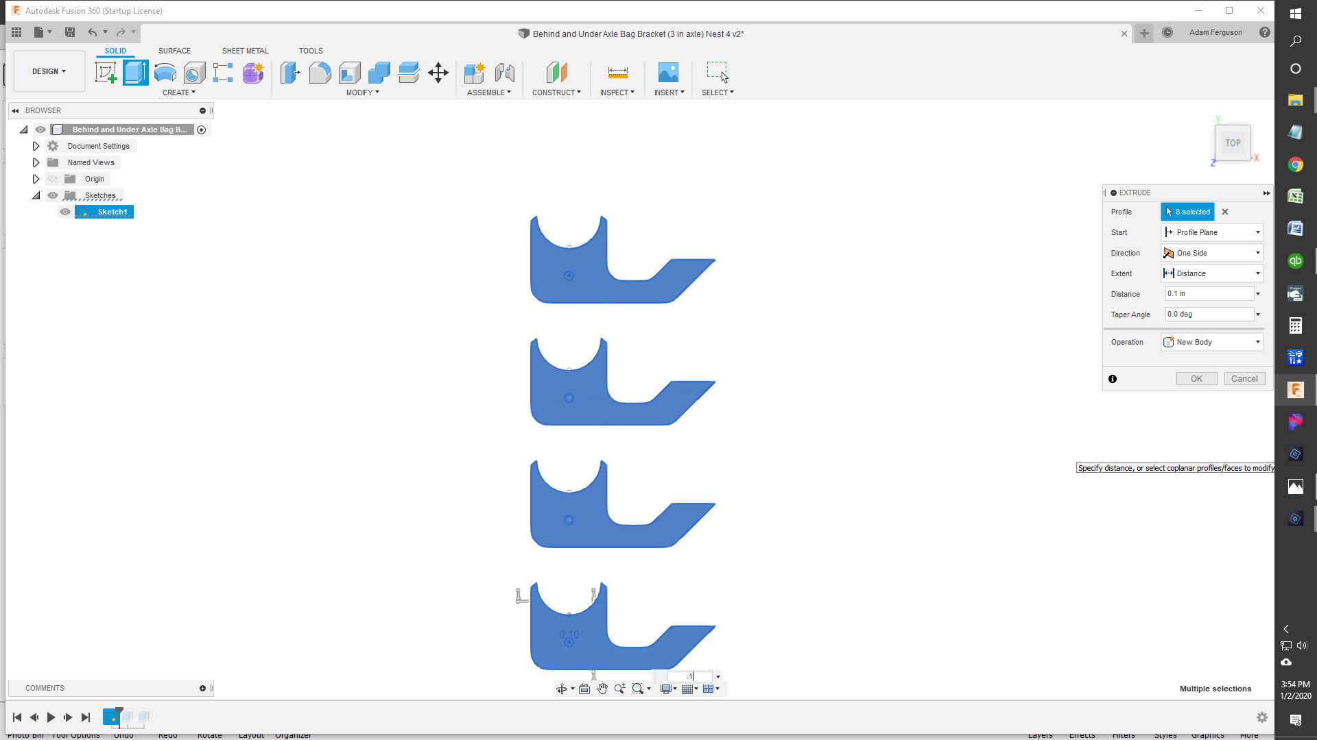
I created a design for a bracket I need to cut out. I put a circle in the body of the shape as a hole that needs to be cut out. I then did a Rectangular Pattern mirror to be able to cut out 4 at a time. Next I select all 4 of the patterns and click extrude. I extruded the design .1 inch as I’ve been told to do before trying to create the toolpath for cutting. This is where I lose my holes that need to be cut out on the body of the bracket design. I can see where they should be after extruding, but they aren’t being picked up by the toolpath. Why do my circles (holes) disappear when extruding?
Have you tried it without extruding? The holes aren’t likely “holes”, just circles so they’re not extruding with the rest of the part. If you don’t extrude I bet you’ll be fine (btw, I almost never extrude in F360 - I think people use that technique to get around other problems with their design objects so it’s a band-aid not a solution and sometimes has its own issues).
I also thought it looked like you “picked” the holes themselves to extrude as well as the rest of the bracket… Thus the “8 profiles selected” in your second image…
Kind of hard to tell from here but maybe just try selecting the bracket parts only and look for “4 Profiles selected” ??
Both of the above suggestions sound great but when I have that problem I save the project and close fusion, when I reopen it they are majicly like they are supposed to be. It seems saving it forces the computer to turn it from a object floating on the page into a part of the piece. Just my 2 cents.
The reason to extrude is to be able to click one time on the body of a design with lots of features to create your toolpath and not have to go back in and reverse your arrows…when you extrude it’s a 3d object and it can tell what’s inside or outside. In this case it’s a simple part and exstruding isnt going to save you much time.
At first, I tried creating the toolpath without using the extrude feature. When selecting the contours/chain of the design, I found that for some reason I was having to select many different segments of the shape instead of just being able to click once on the line, or border, of the shape. I figured I would try extruding to eliminate having to select so many segments when creating the toolpath.
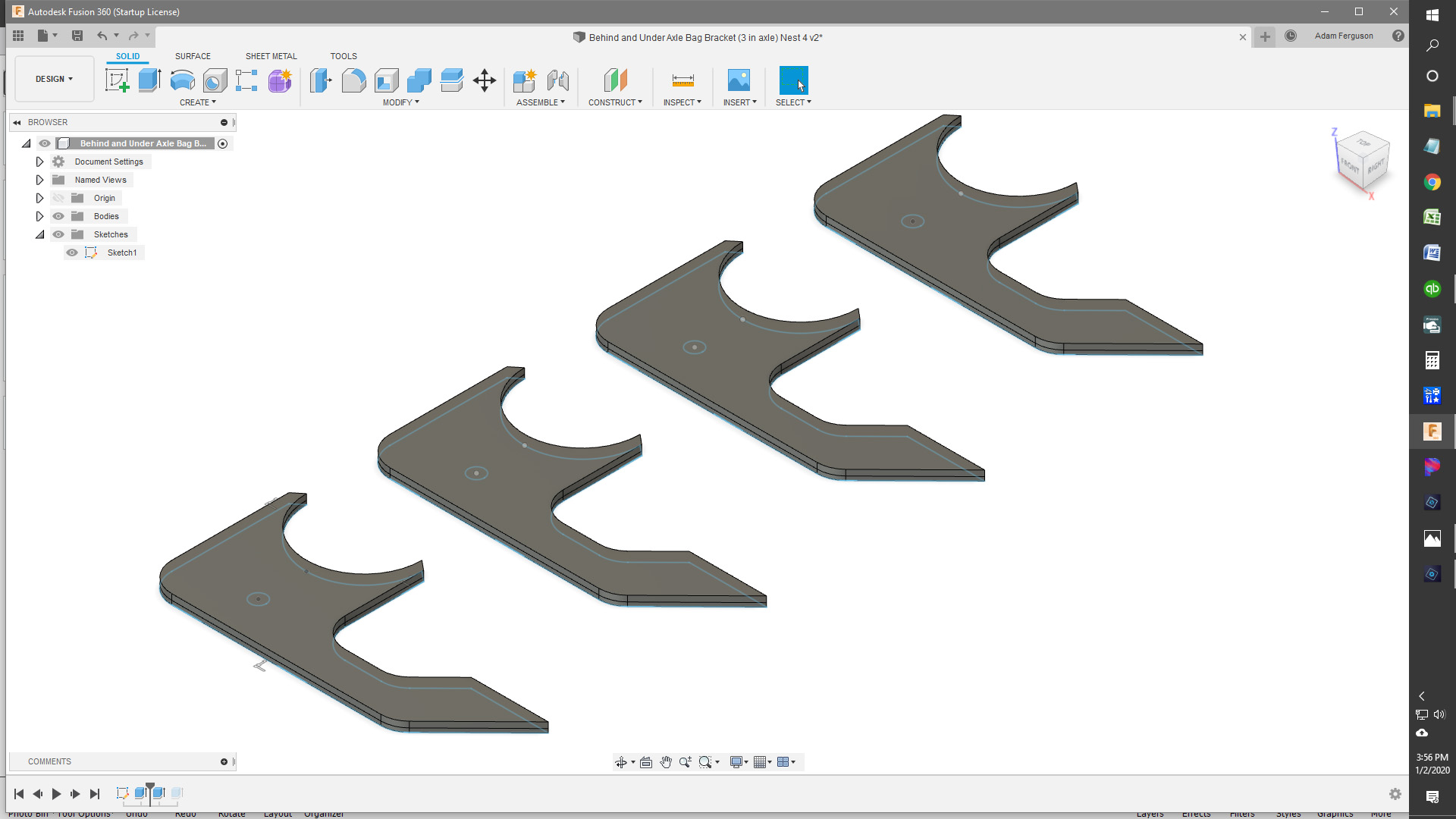
Today, I went back into fusion and decided to start over and try again. I copied the design into a new untitled program in Fusion 360. I made sure all my measurements/dimensions were correct and then extruded the design. But this time when I selected the part to extrude, I didn’t drag the mouse over the entire design, I simply clicked on the interior of the shape. I noticed then that the part was selected as well as the outside edge of my hole! Next, I did the rectangular mirror to create 4 of the same object as a nest. I proceeded to create a new setup and generate a toolpath. It worked perfectly and I have already cut the parts out. Now for some welding and I’ll be ready to install
Glad you got it and after reading about the problems that some are having with fusion, I’m glad that I gave up after less than a week and went back to what I knew.
The lines weren’t a single path. They were essentially separate objects/vectors. That’s what I meant about extruding solving the toolpaths problem but not addressing the underlying drawing issues.
What you did to fix it by redrawing it correctly is what really should be done but it’s usually easier to extrude and move on. In this case fixing the drawing also got you a proper extrusion with holes that were holes
Install sketch checker and run it before you try to make a toolpath next time.It will show you if your lines dont connect.If I insert a dxf or svg I run it right after and fix all the broken lines till I have no open loops.
I find imported designs are the worst. It makes you wonder if people ever cut the design with any kind of CAD or if it came from some Cricut machine or something Sketch Checker is a great Fusion add-in.
I installed the sketch checker thing before Christmas when u was working on an svg design of a forest scene. I couldn’t tell that it was doing much when I used the sketch checker. How does that show that lines aren’t connected? All I saw pop up was a bunch of dots but when I zoomed in on the dots, the lines were clearly connected.
If the dot is on a line its broken.You can just trim out short segments and redraw to connect or sometimes I use the arc tool and trace over the dot then trim out the segments under that dont connect.Its not without flaws.If you have the trim tool active when you scan fusion will crash and have to restart so exit out of any tools before you do.After you fix one broken line you will need to rescan to show the remaining broken lines till you get them all.Any small lines that are imported that aren’t part of your sketch will show up as a dot too.Once you fix them all you will get a pop up saying no open loops found and when creating your toolpath you will be able to click the each detail one time instead of clicking multiple segments…if you exstrude you will just click on the body of you part one time to select everything.