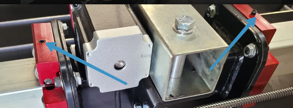
Hey i just measured the blocks thay are the right blocks.
I have another question about the bearing block bearings on the carriage weldment. some of the bearings you can’t move your finger. Tried to adjust the bearings but when I tighten the bearings back up they went back to the same place.
I would go back and review this part of the assembly.
Not all these bearings will end up at the same amount of slip. Depending where they are on the tube some will become tighter and looser. It was never the intent that all of them are touching the tube hard at the same time.
Yes sir i understand that and not all of them are touching. When i put the table together i payed attention to that part of the instructions. At that point everything moved freely up and down the Y axis.
I just went back and loosened the adjustable bearing block acouple of the bearing that are not adjustable are the ones that don’t want to move freely. For about the first 1/2" it moves fine then it looks like one side of the Y axis moves ahead of the other side and binds up.
Well I would sight down both rails then( if you’ve done all the steps correctly) to see if one’s bent.
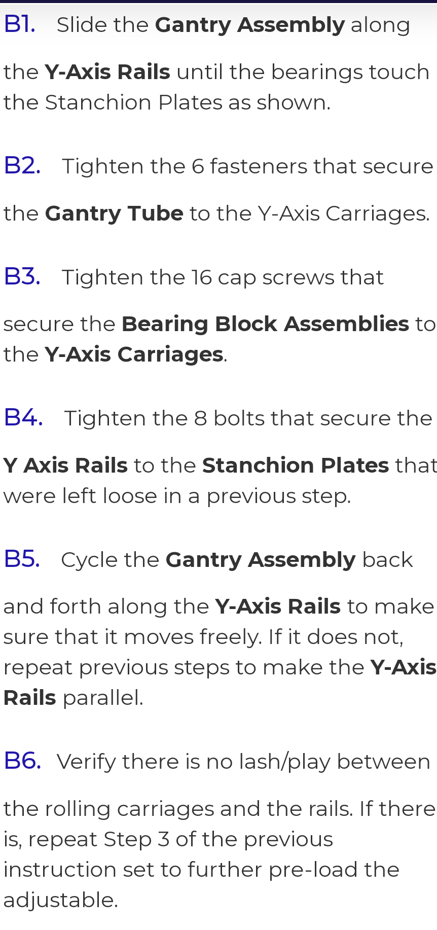
Sure seems like there is a considerable amount of adjustment difference between these two screws.
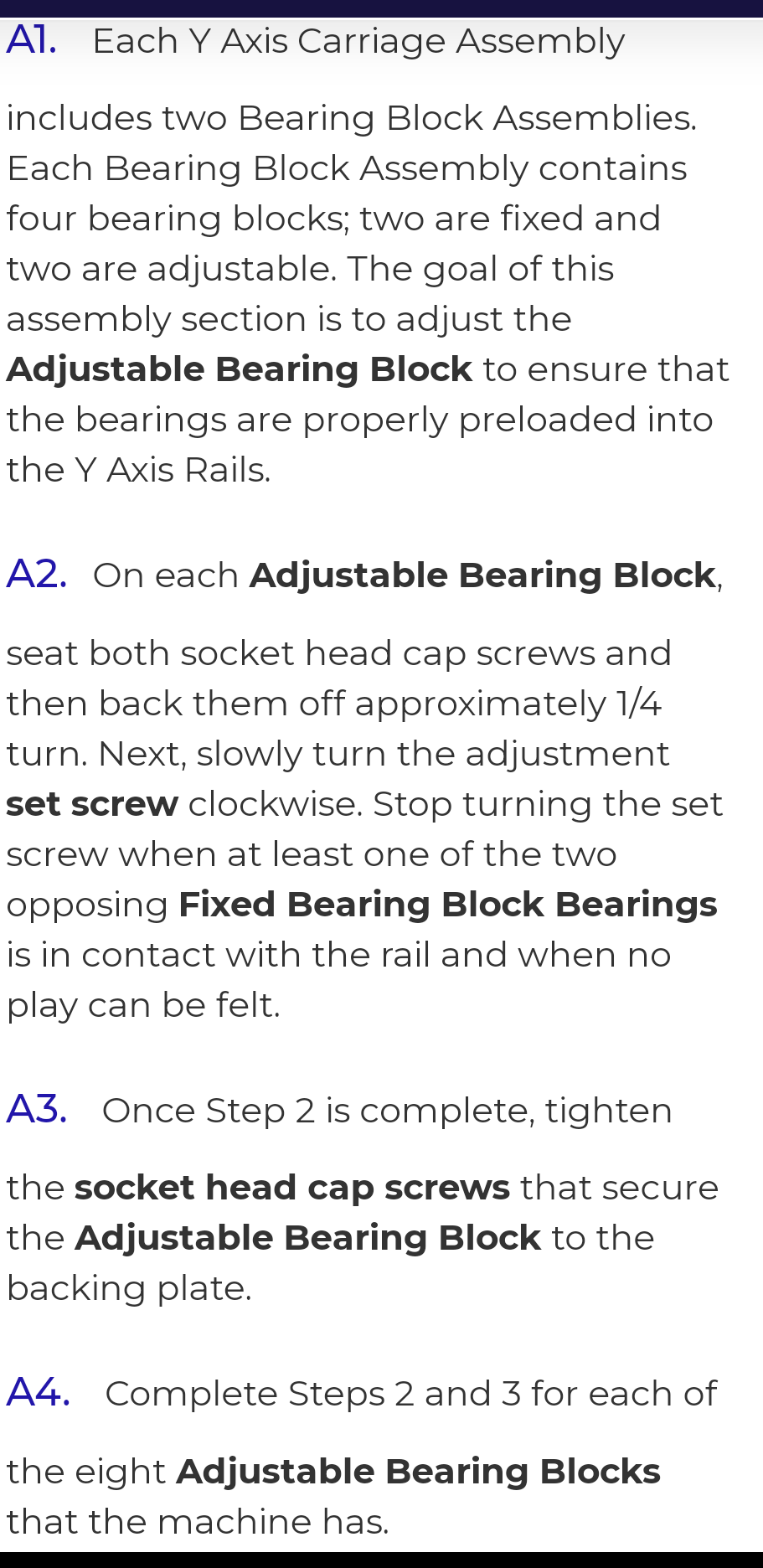
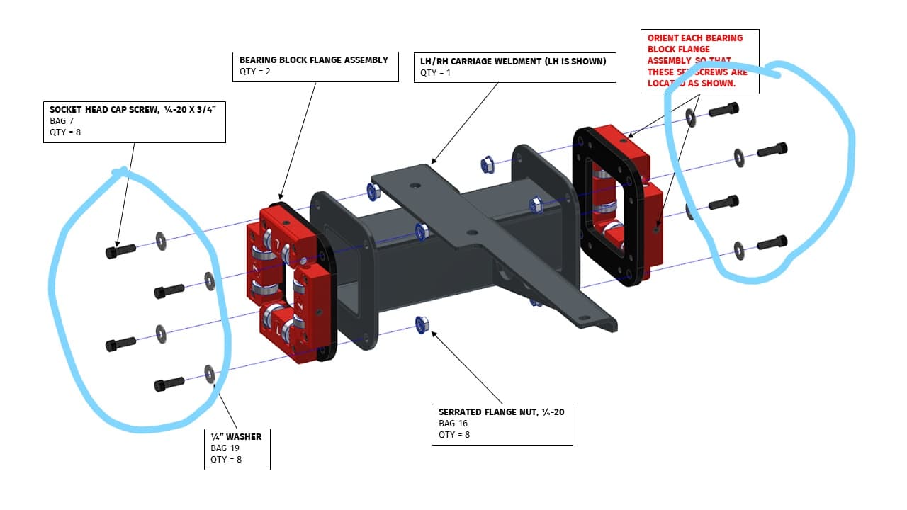
I know you’ve seen, it but here’s the instructions for that part of the assembly.
Any other members out there feel free to jump in on this one.
Well ok going to go through it again. If I can’t find anything I’ll take the bearing block and weldment of and look at it also will post agian sometime next week thanks.
1 Like
The 2 adjustable bearing blocks on each group of 4 are used to adjust all 4 sets of bearings in that group. You need to loosen the 4 bolts that hold the assembly onto the weldment, so that the whole block can move when you adjust the 2 adjustable blocks. Leave the bearings looser than you want them, because they get tighter when you tighten down the adjustable bearing blocks.
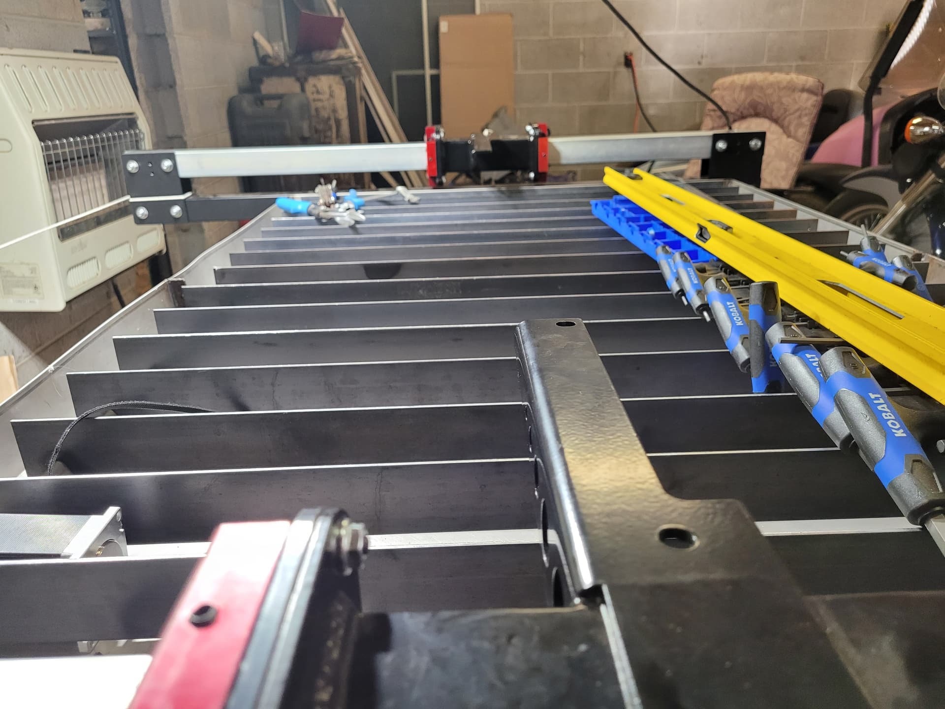
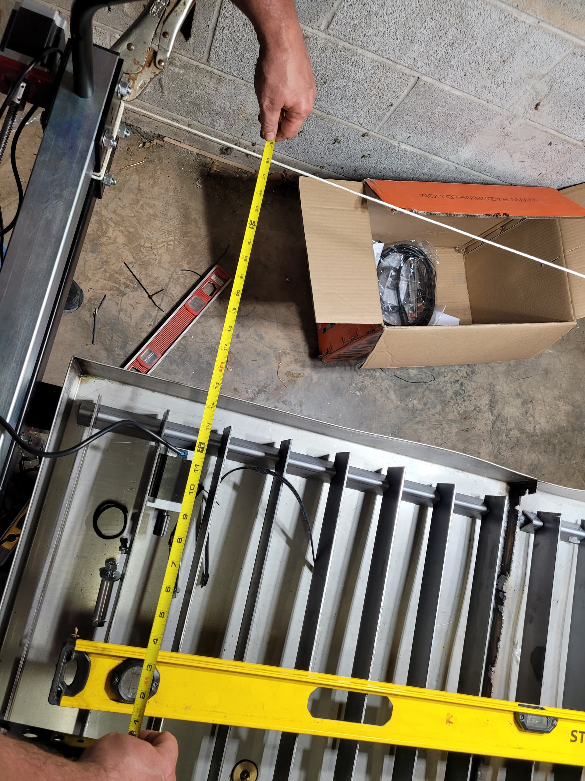
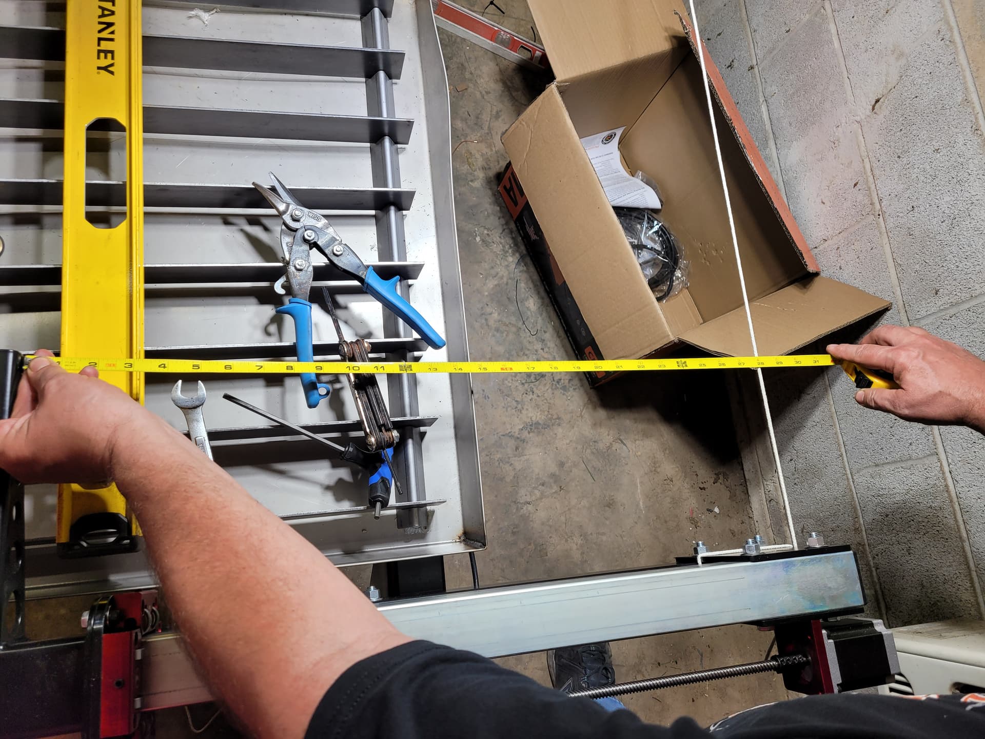
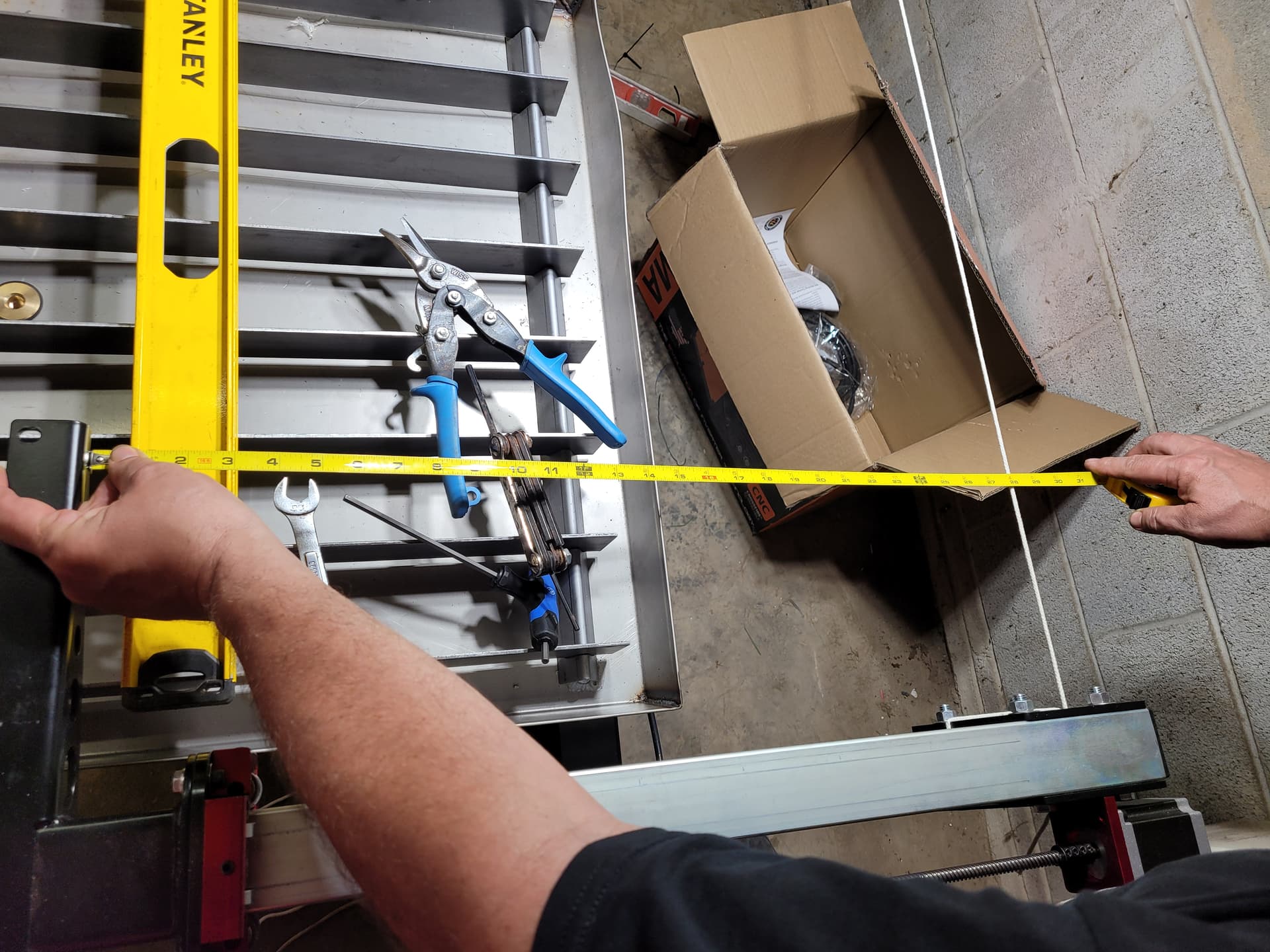
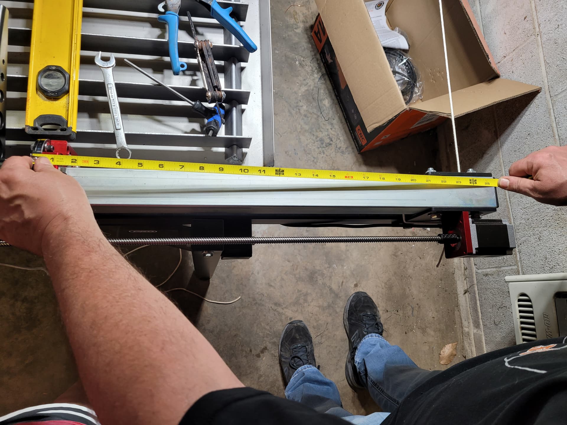
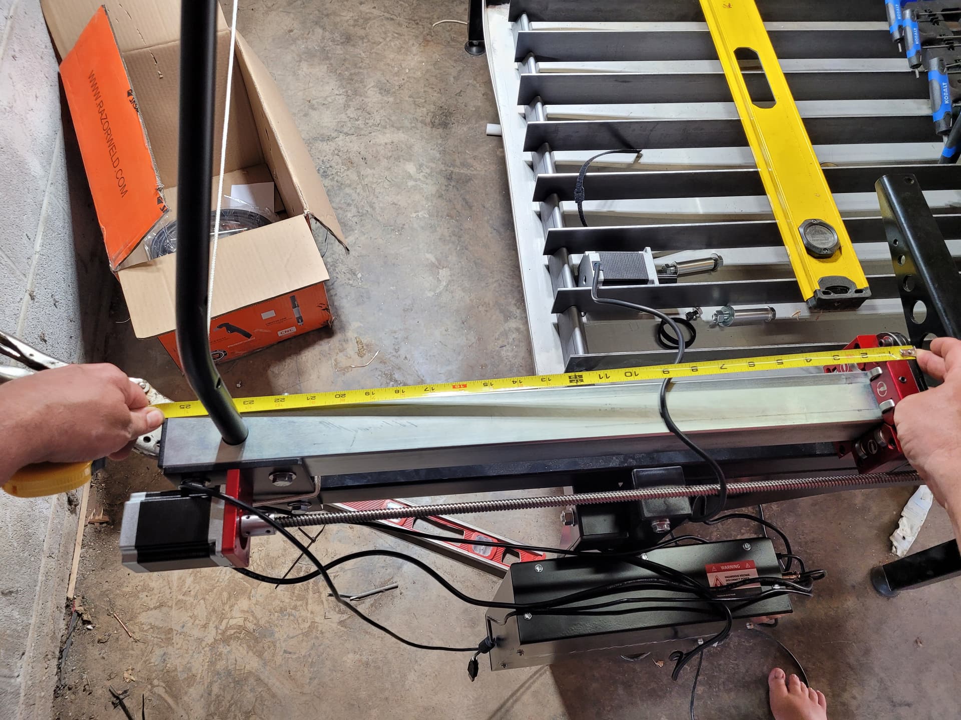
Ok guys so i took off x axis today just to get a better look at the weldment and bearings it looks a little bent to me so i took some measurements and discovered it is a little off first i measured 25 1/2 from back of weldment to the frame on both sides
Then i run a string for a straight line and measured 27 “15/16 on the right side and 28"3/8 on the left side and yes i also measured corner to corner and got 78 1/4” on both sides so with the weldment being 11/16" out of square and the x axis is installed on top of the y axis would that cause the bearing blocks to be pulled tight against the Yaxis rails
An help would be appreciated thanks
If you loosen these 4 bolts on each side of the weldment, you can move the weldment around to align it. There is also a lot of play in the bolt holes that mount the X axis to the weldment, which is the reason why you run both Y carriages up against the stanchion plates on the front of the machine before tightening the 6 bolts that hold the X axis rail to the weldments.
1 Like
Tin and ds690
Did one of you tell me langmuir had a bad batch of lead nuts?
I have already had to get a new nut for the x axis because langmuir sent the wrong lead nut.
Now i took the y axis lead screw out of the nut and discovered that the threads look different. Do you thank the threads are different?
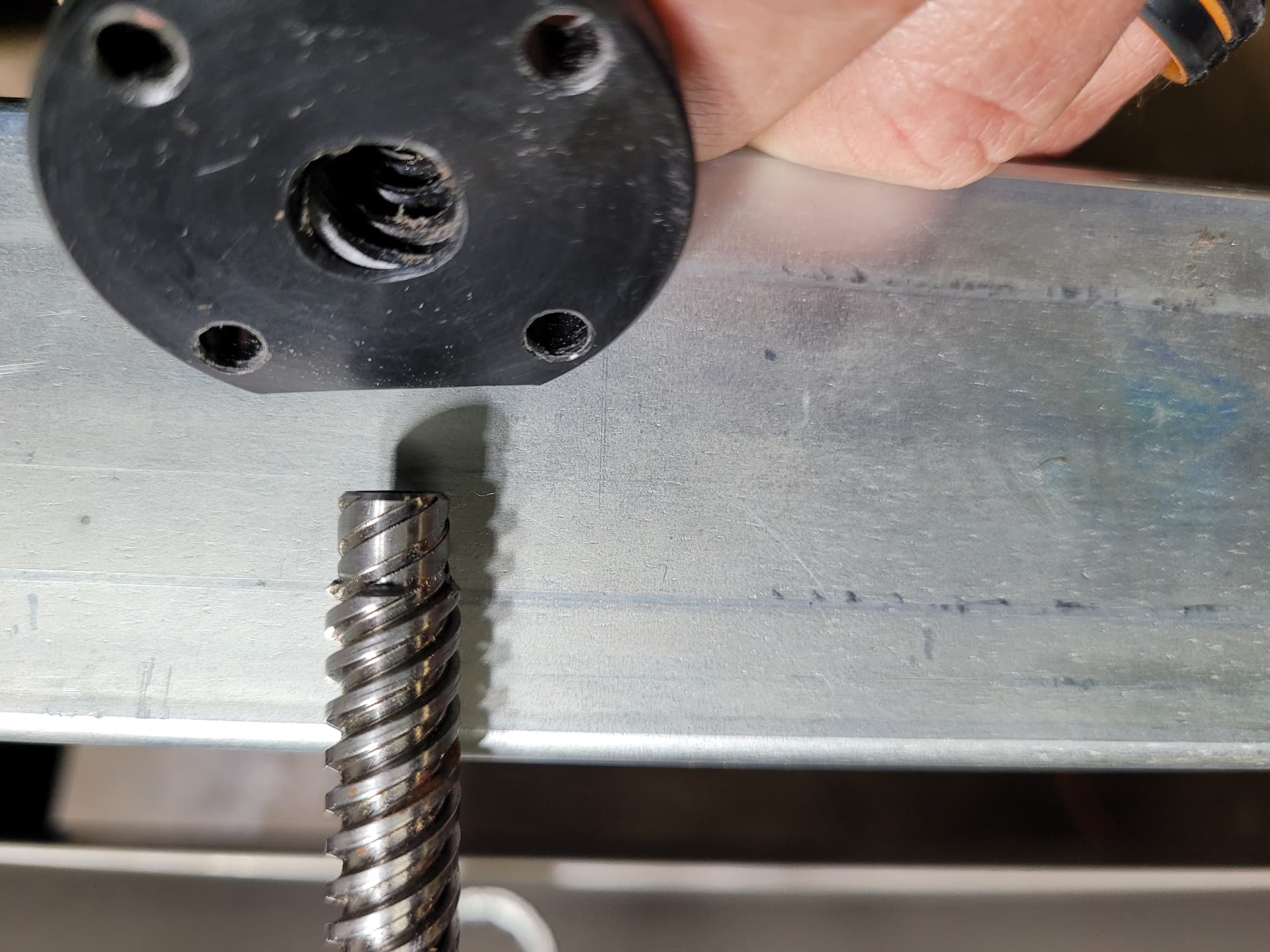
That does appear to be going the wrong direction. They did have some other handed nuts accidentally mixed into a few batches.
I haven’t seen one on the four bolt hole nut yet but it does appear to be going the other direction.
Ok thanks i will get ahold of langmuir and see what they say.
Thanks
Based on this photo, the threading appears to be in the correct direction. These are cut on a CNC lathe and then chased with a tap to produce the final form. Are you compressing the white collar when trying to thread the Lead Nut onto the Lead Screw?
Yes sir I am
Going back over everything agian will let you know when its back together
Thanks
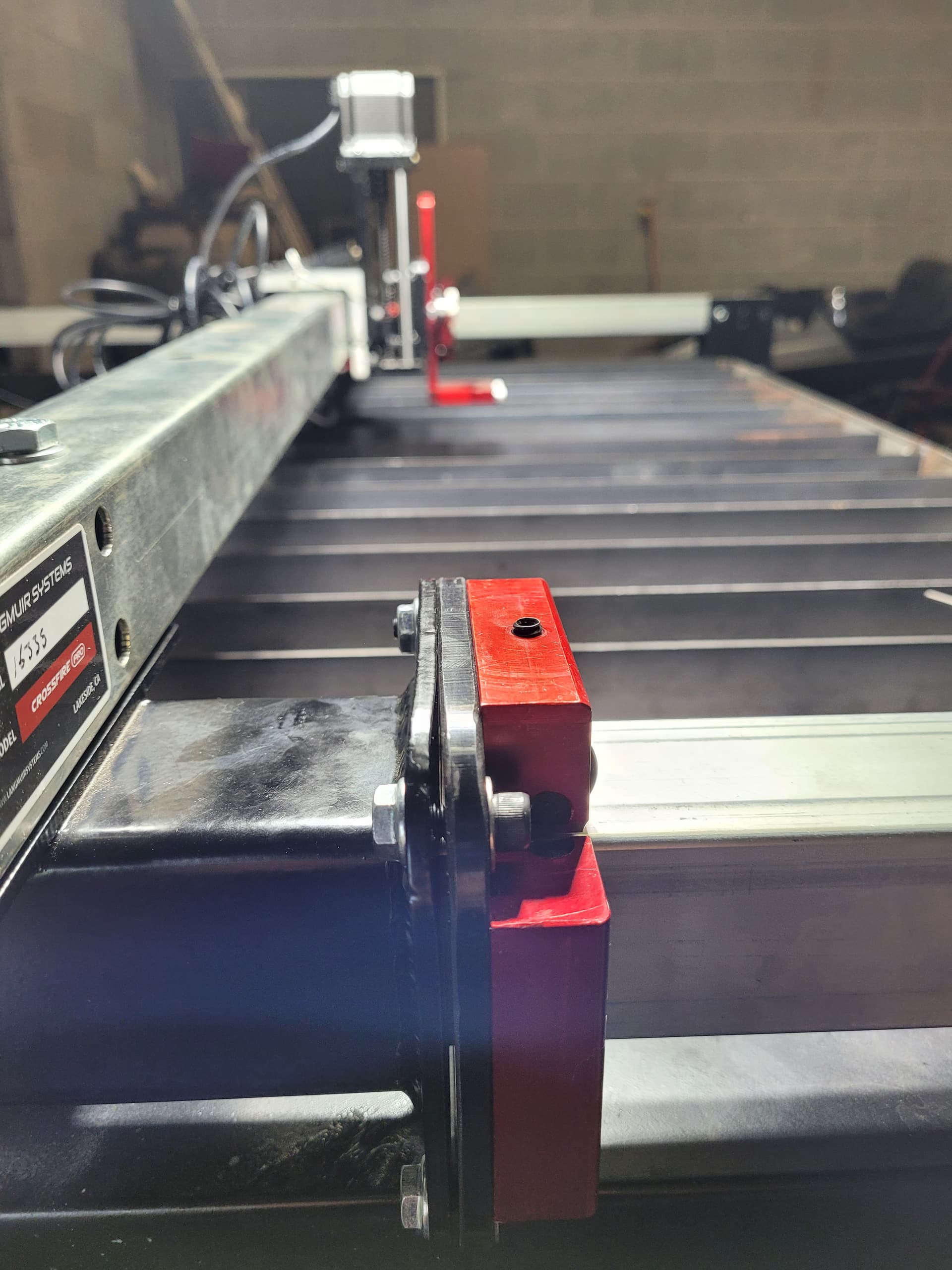
Ok tightened everything against the stanchion like I was instructed to do. But when I tightened bearing plate to weldment noticed it pulled bearing plate making the bearing tight against the Y axes
Could something be wrong with weldment or bearing plate. Trying to adjust bearing block back to where it was when I preloaded the block.
Any thoughts on what is going on please let me know
Thanks
Just wanted to ask lf leaving a gap between the bearing plate and weldment will be alright? Really don’t thank this is the right way to do this but it’s the only way I can get back to preload conditions.

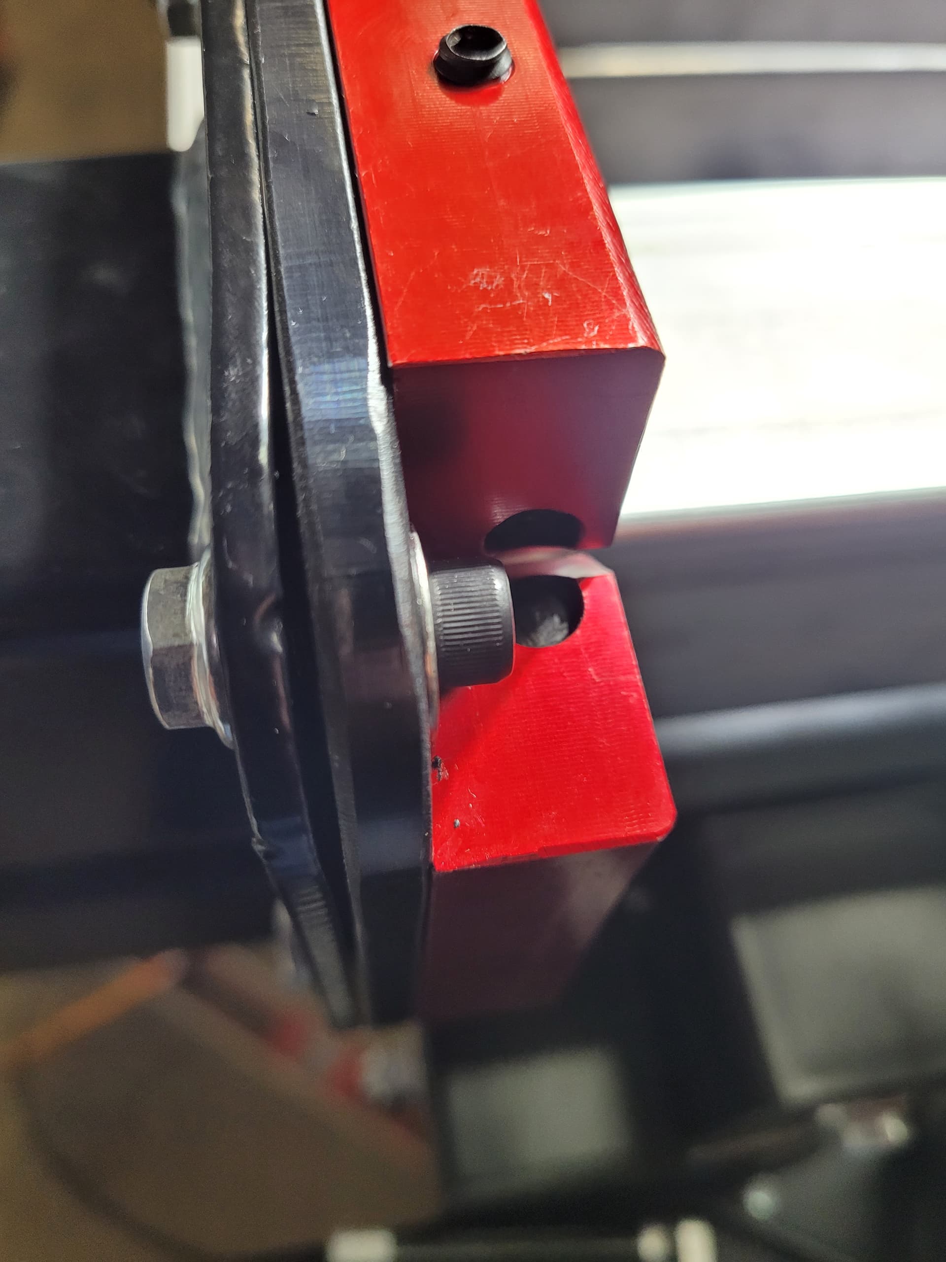
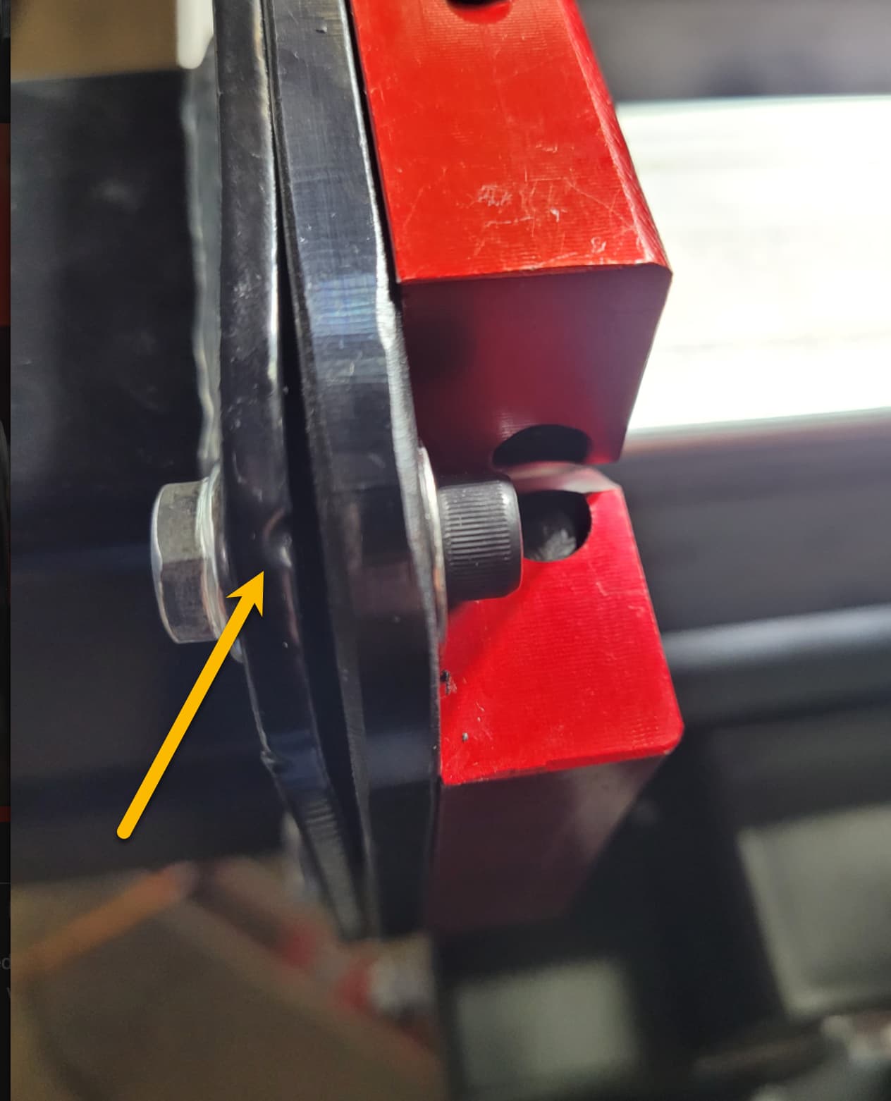
Interesting ‘twist’ on locking the bolt…
That’s broken in my book. But that’s just me.
The flange on the weldment clearly looks bent in that photo. I’d unbolt that bearing block and attempt to bend that flange back.
Get a long adjustable wrench and close the jaws on the corner of the flange and try to use the leverage of the wrench to bend that flange back to something resembling flat.
Weldment looks bent to me, like it got dropped and landed on that corner. There is a nice ding on that corner as well. What’s interesting is it looks like that ding was there before it was powder coated…
Thanks i thought the same thing.