Can you post your NC file or TAP file or/and f3d file?
the actual file or a screenshot from sheetcam?
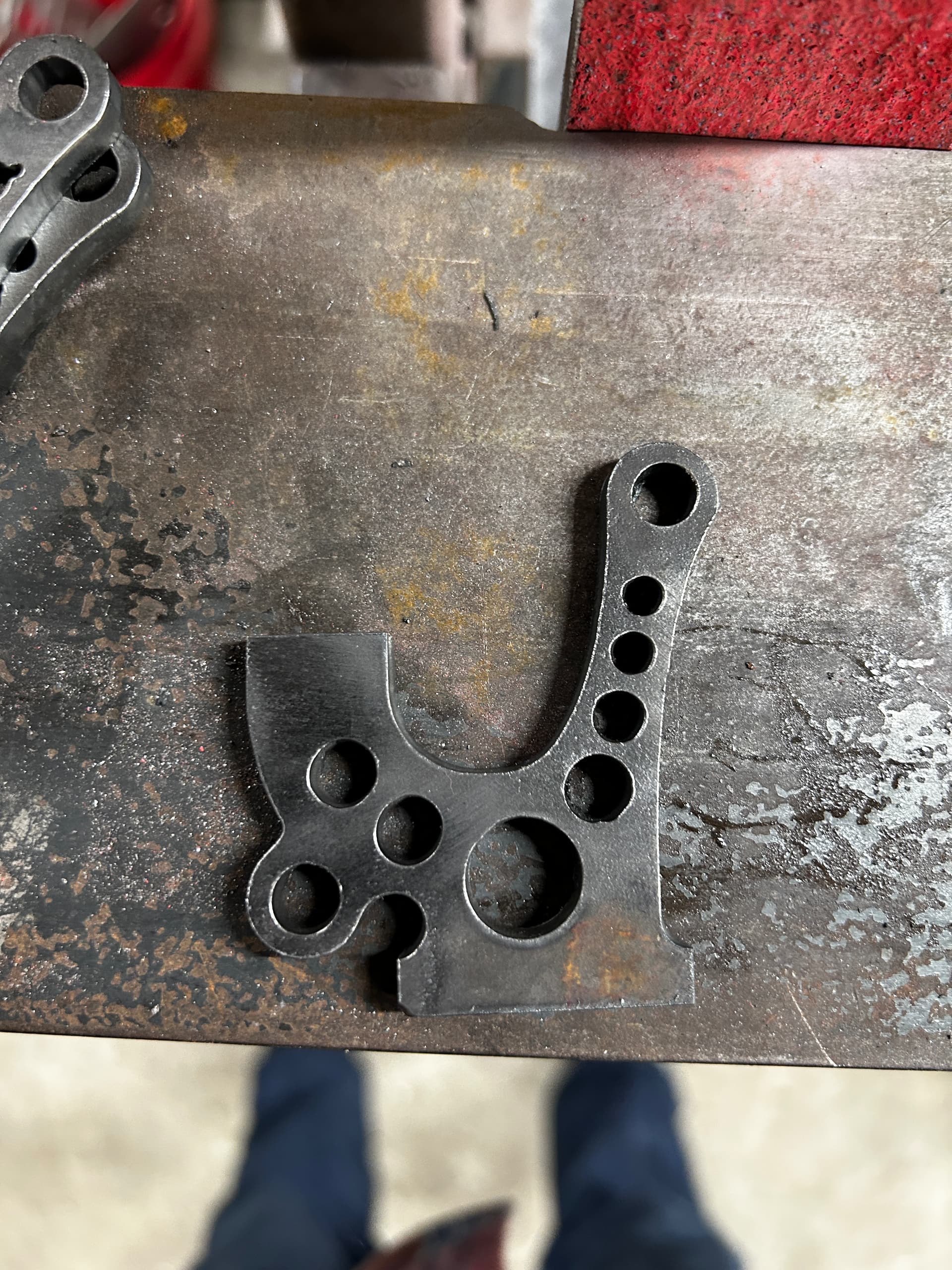
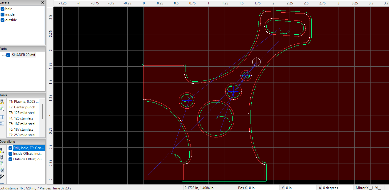
The little divot looks like where the lead in meets the actual cut path.
I never use lead outs, on anything. But lead ins like this could be helped with an arc that closely matches the actual cut path starting close to the center.
I run holes on lots of steel as I’m a parts guy, not a sign maker.
Start them all in the middle. I think it’s a mechanical issue with the lead screws and motor coupling.
So if your CAM is correct, and you suspect it’s a mechanical issue, begin with seeing if your Z-axis assembly wobbles at all.
If it’s loose at all, adjust and tighten the eccentric bearings slightly to tighten up the assembly (not too tight).
Then go ahead and make sure your Z-axis assembly is properly trammed.
Cool I’ll do that. After cleaning the lead screws there was a lot of improvement. But circles are still a little wobbly.
If it’s anything else, these guys will figure it out.
While there may not be too many eyes on the forum, they have tons of combined experience.
Both would be good.
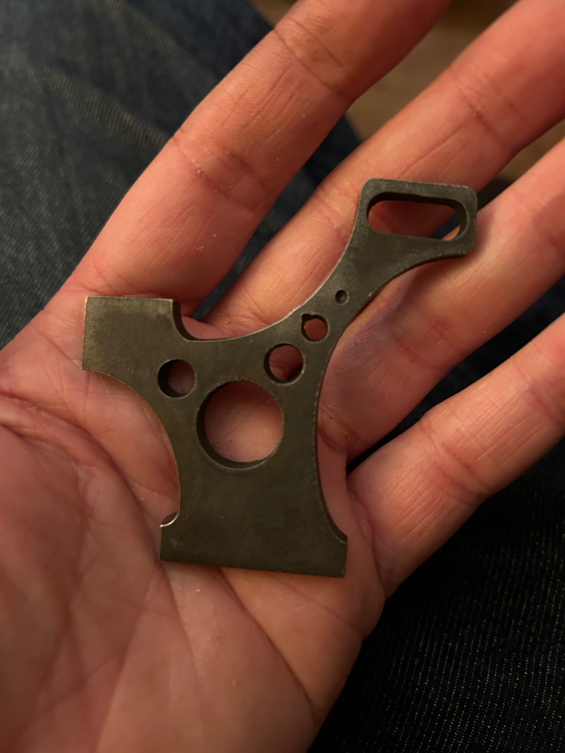
Here’s an older design that I have been cutting with no issues until now. Checked each axis and motor couplings everything looks good. Cleaned and wiped down surface the axis rolls on with wd40. Circles look good but top hole has a little error.
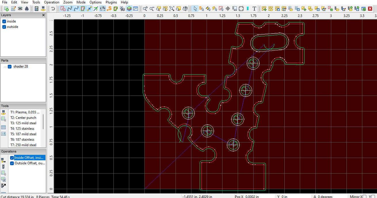
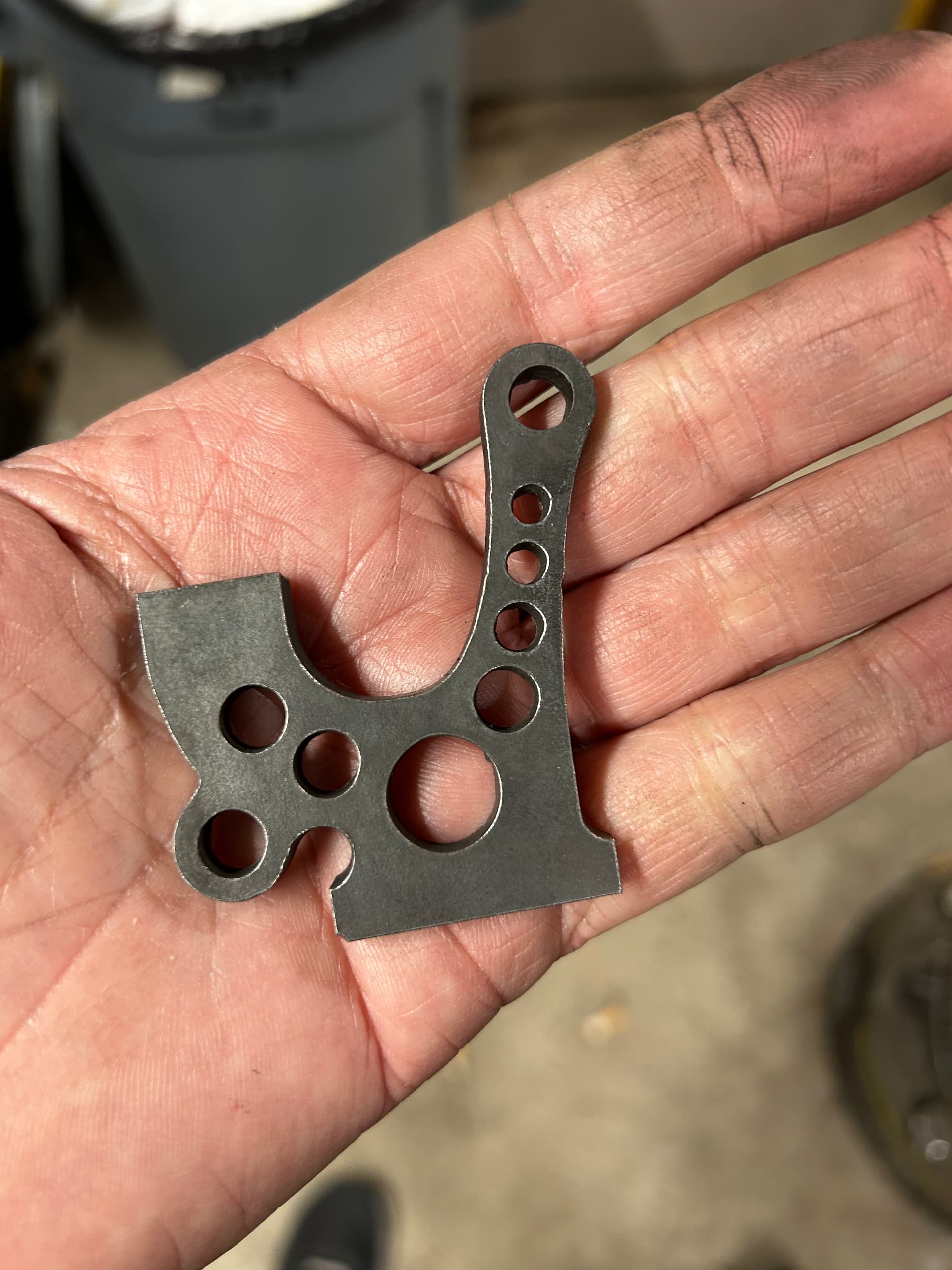
If you look at the screenshot of your new one you aren’t starting in the middle.
When the blue crosshairs are engaged in sheet cam that indicates you’re starting from The middle like in your older design.
I would also try to get rid of the lead outs entirely like @Kwikfab stated.
Cool. Got rid of the lead outs and added a 1 second pause at the end of each cut. Thanks!
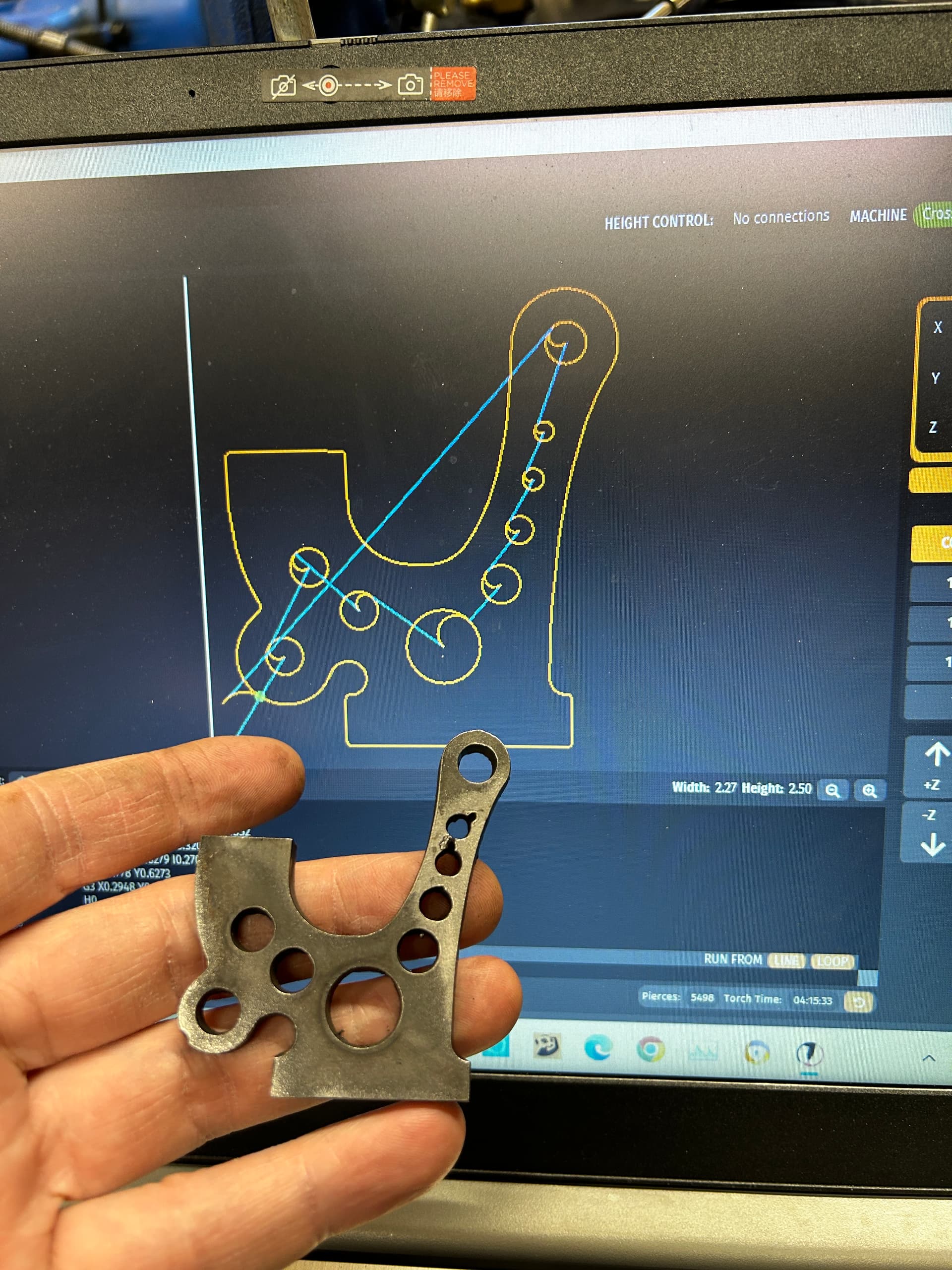
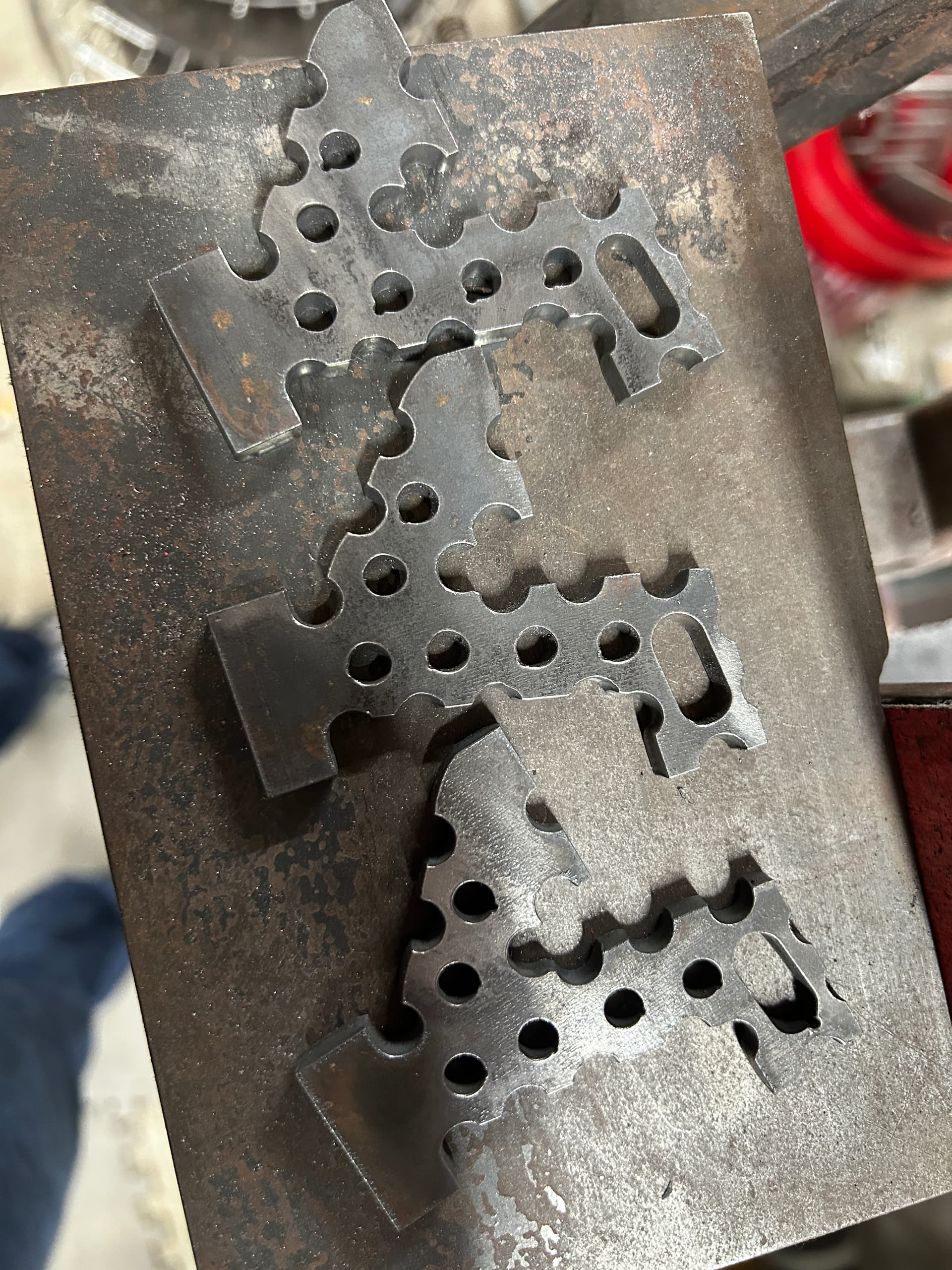
.75 pierce delay 1 second pause after each cut. No leadout starting from center. Weird cuts on circles that don’t fall in any path. I don’t get what’s happening. Seemed like it was torch still running while traveling to next cut but these weird lines don’t follow that path.
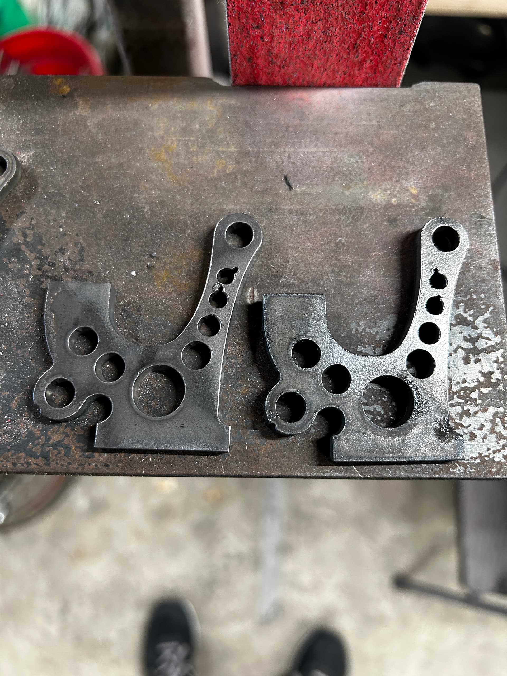
Did another piece on the right without any changes and the lines are in a different spot. Must be a mechanical problem.