Couple of things to know here. Just installed a machine torch and I am also moving away from F360(have to many problems to describe) to sheetcam and affinity designer.
CrossFire Pro with THC
Everlast 52i
Fire Control 21.1.5
I installed the machine torch and everything seemed to be fine. Like I said above trying to migrate to sheetcam. Watched some videos online on how to set it up so I assume three something wrong with a config somewhere. When I import the tap file into fire control and run it the torch goes down touches the material and then immediately raises up going to the top of the z axis topping it out as you can hear in the video and then firing. I am not sure what the issue is.
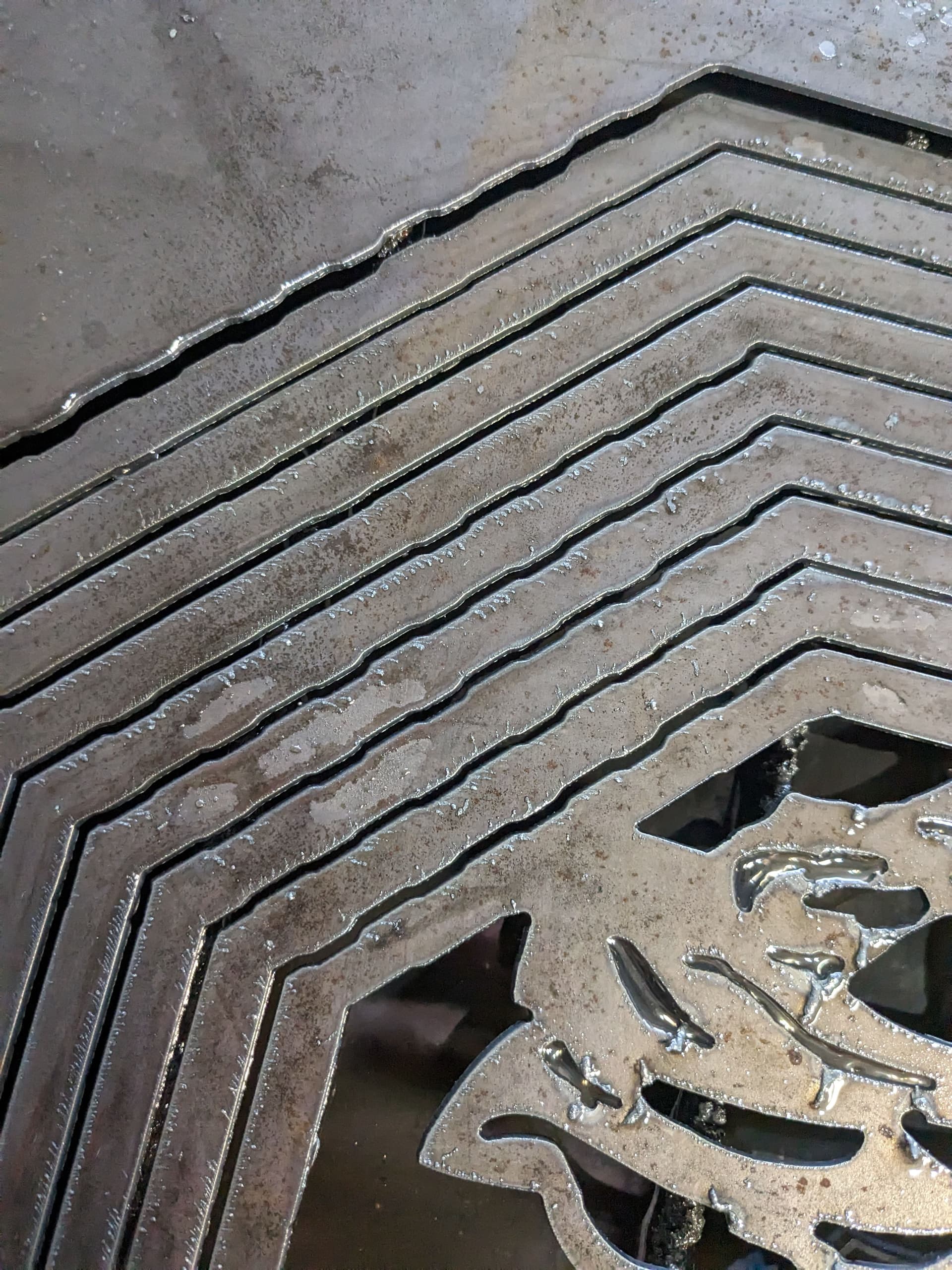
As a test a ran NC file that I had cut before just to make sure it was an installation issue of the machine torch and that file ran like it should although I have wavy cuts now, not sure what that is. I have read a bunch of different things that can cuase that from loose screws, to slow speed and THC adjusting. The orginal NC file I cut on stainless and the speed was definetly slower than my test running on 16 gauge mild so could be the issue.
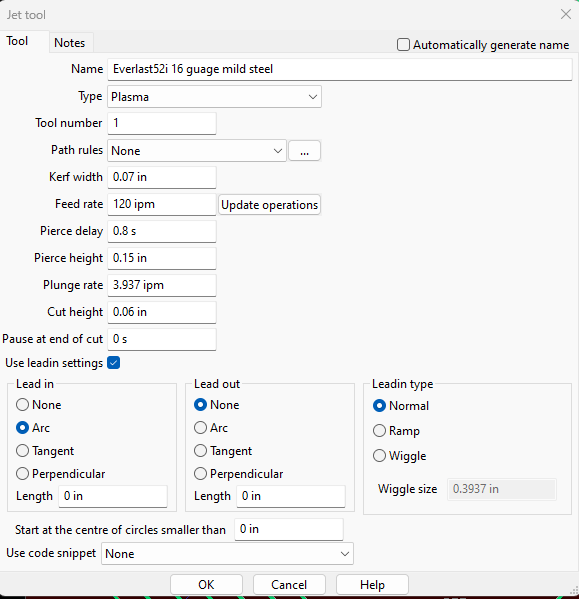
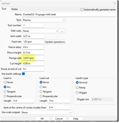
Your Sheetcam file has a pierce and cut height of over 2 inches.
I’m thinking this might be a units issue that can be changed in the settings. I’m not near my computer right now to be able to direct you to where you change the units
@ds690@Kwikfab@72Pony Thank you for the response. Pretty new to sheetcam, got a bit of a learning curve heres my tool cofigs and post. I am sure i am missing something some where I just dont really know where to look just yet.
Like you I use Fusion so I can’t help you with the sheetcam settings. I just opened your TAP file in notepad to look at the code and noticed the pierce and cut heights. SheetCam default for plunge rate is 3.937 ipm (F3.937 in your code). Fusion uses 100 ipm. I think most sheetcam users are between 60 and 100 ipm for their plunge rate.
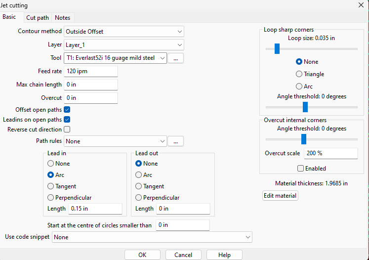
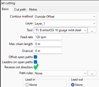
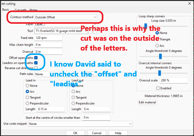
Turn off the “offset open paths” and “lead ins on open paths”. Turn on “reverse cut direction”.
Set plunge rate at 60ipm or more.
Kerf of .07" is excessive. Try setting that to .05"
I don’t see anything wrong with the values in your tool for pierce and cut height, but they are being calculated differently in the post processor. Did you type the “in.” In those fields, or was it already there?
Edit: I may have found the issue. You have a material thickness of almost 2" showing on the jet cutting operation screen. That is probably being added to your programmed heights. I always leave the material thickness set at zero. You probably have to go into the options menu to change that permanently.
Ok I changed all the values to what you have recommended and will test it and give an update later. As far as the ‘in’ in the fields they were there. I appreciate the advice!
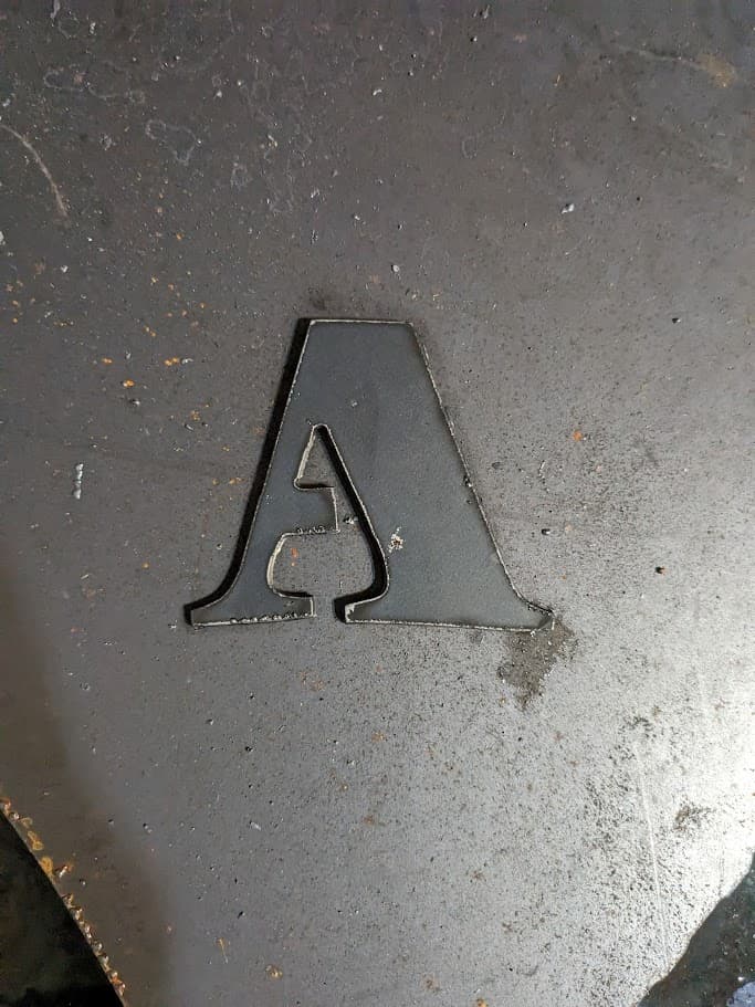
You were correct the material thickness was it, thank you so much for the help. Love this forum. I cut a piece out much smaller than the original file but I did not notice any wavy cuts this time either but I will test that out more tomorrow but it was a successful cut.
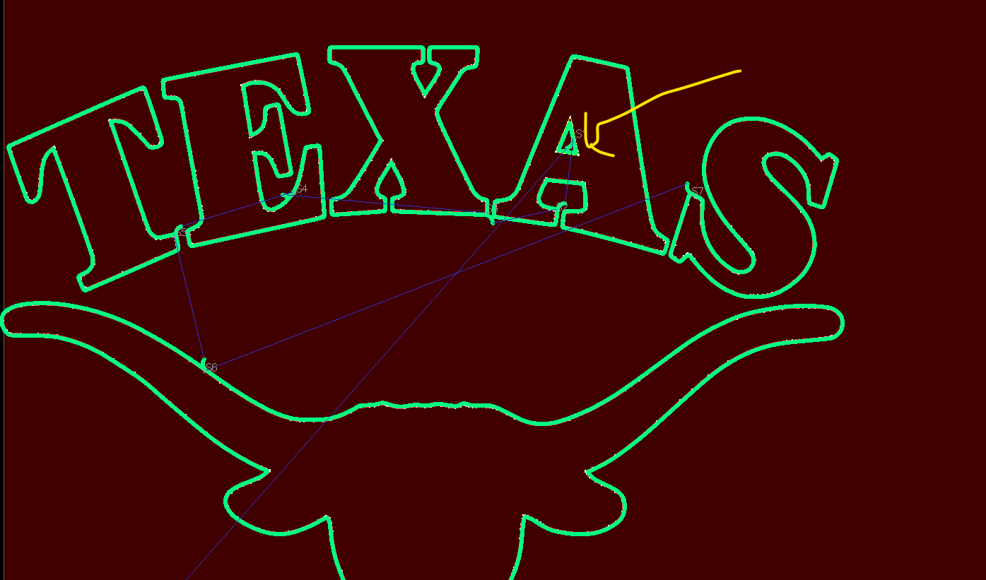
Does sheetcam automatically add bridges to letters. My DXF file did not have a bridge there but it added one on the ‘A’
I think you are looking at the lead-ins and they are on the wrong sides of the letters and the bulls head.
I am assuming that you meant to cut out the letters and the animal head? This cut is going to drop all of those pieces out individually as the finished parts.
I understand that layers are regularly used in SheetCAM. Are all inside contours put in one layer and all outside cuts in another layer? Is that done automatically by SheetCAM?
Well it doesn’t use layers you can though. Sheetcanm is usually very good at identifying inside and outside cuts. It will make yellow lines for inside and red for outside. It will automatically cut on the correct side of the line when you offset it correct. Sometimes it does get it wrong. Then say you want circles cut and you just cad a circle you would need to change the offset depending on if you want a hole in your material or you need the circle you are cutting. Just depends on what is the scrap side of the cut.
If the are no issues with the drawing, you should be able to use “outside offset” and Sheetcam will assign the correct offsets to inside, outside and open paths.
There is usually no need to move things to separate layers for different offsets.
What usually will screw that up, is broken paths on the outside contour. In that case, Sheetcam assumes that the first closed contours are outside offset.
The other thing that will require you to select “inside offset”, is when all of the cuts are inside cuts and there is no perimeter cut. Such as, cutting letters out of a plate that is already cut to size.
Yeah, still trying to understand all that is Sheetcam. I see the a is yellow so that is an inside cut. In my new operation I had unchecked offset open paths and lead ins on open paths and only checked reverse cut direction
With regard to those two fields that I told him to uncheck, they only affect open lines. You generally want them to cut the center of the line and not have lead ins