I’m looking to rewire this control box as it should with the Torch ON/OFF input.
Can anyone shed some light as to how it should be wired? Share a picture of the actual wiring? Wiring Diagram?
I’m looking to rewire this control box as it should with the Torch ON/OFF input.
Can anyone shed some light as to how it should be wired? Share a picture of the actual wiring? Wiring Diagram?
Welcome to the Forum!
What plasma cutter are you pairing with your CrossFire?
Here’s the Plasma Cutting Wiring Guide from the CrossFire Assembly Guide:
https://www.langmuirsystems.com/crossfire/assembly#plasmawiring-section
Thanks! So this is a Gen 1 Cross fire using a Hypertherm 45xp… Its been a while since I’ve looked inside the box needless to say. I had it wired with a pressure sensor to stop the running program in the event of low pressure so I added a relay and rewired a few things…
I went to the link you provided but that doesn’t really show much of how to wire the plug for the Torch On/Off and which pins to use on the control board… Any specific info you can share?
None of my business but:
My Hypertherm 45xp will stop firing automatically if the pressure drops too low. If it is too low to start with, it will throw an alert on the machine and not even attempt to fire.
Not the issue but I appreciate the help.
What I’m looking for is the wiring diagram of the Torch ON/OFF plug. Which plasma cutter is plugged in should be irrelevant in this case since I’ve removed the pressure sensor and trying to revert back to the original wiring.
Maybe I am confused what you are asking for but there are only two torch on/off wires and polarity doesn’t matter. Hope that helps.
@erengineering is this what you’re looking for?
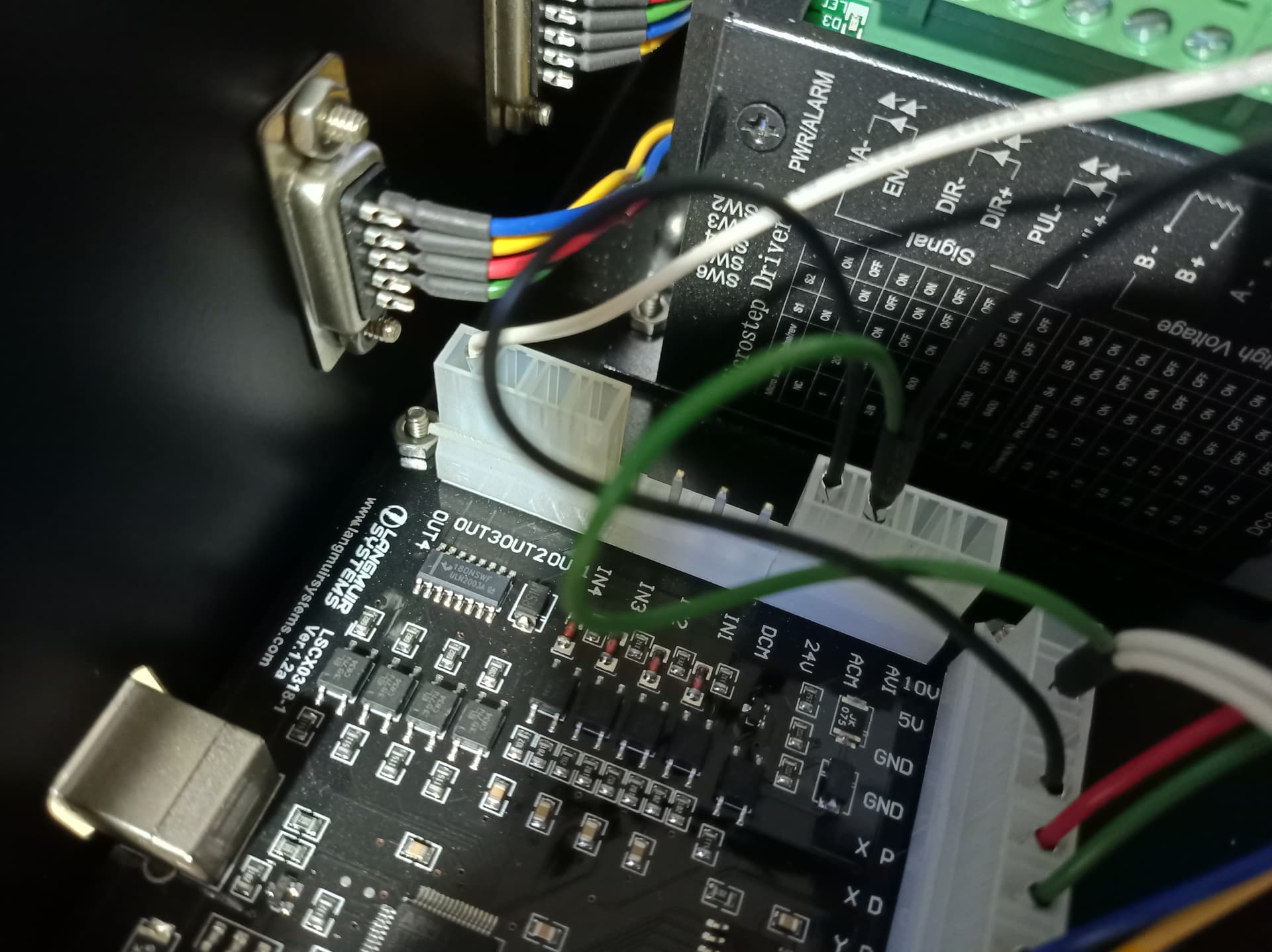
This is how it’s wired internally on the first generation crossfire control box.
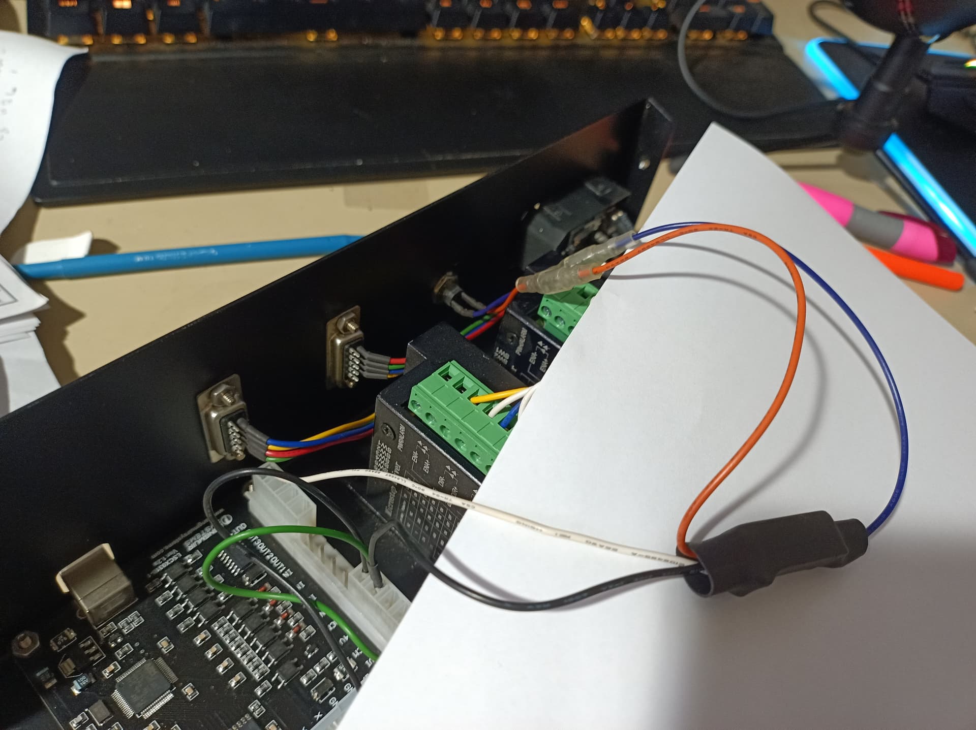
It starts off as the orange and purple wires coming from the torch on/off port and then ends up terminating at the PCB white to out 4 and black is paired up with a green wire and connected to 24v.
Perfect. Just what I needed. Thank you.
Almost correct. The termination is 5V in the OG Controller and that little gizmo in black heat shrink tubing is the Torch Relay. The orange and blue leads go to the COM and NO pin, while the white lead goes to Out4, Black Lead to V+ (I believe) but that extra green wire comes from the PCB’s 5V pin, not 24V.
Now, those of you who have been around this forum might ask how is it that TW has these photos since he has a Gen 2 system… I’m telling you, he has ALL the documentation known to man… Manual Man will strike, one of these days. Mark my words… ![]()
I bought a used 1 gen control box off kijiji sometime ago to check it out.
I see that but 24v in what is written on the PCB next to where the black wire goes to, then then green jumps over to the 5v plug from there . I should bust out the multimeter the check what is happening.
good too know ,I assumed but was going to cut off the shrink wrap.
Who does that???!!! ![]()
Tom and Tin, you are both the best.
Save your multimeter, that pin is normally a 24V INPUT, but LS, using a 5V relay, wired it to 5V instead.