I’ve now done this 20 times on different files, and this is the first file that when I’m done selecting all the outlines to cut, it only generates g-code for a few of the elements and gives an error. I’ve seen that error before when the areas to cut are too small for the software to generate a path. but that’s not the case with any of these. I deleted all the cutting and setups and started from scratch, and it did it again. Interestingly, I had to redo this file (the frame wasn’t the right size). The first time, it worked, it’s only now that I’m running into this.
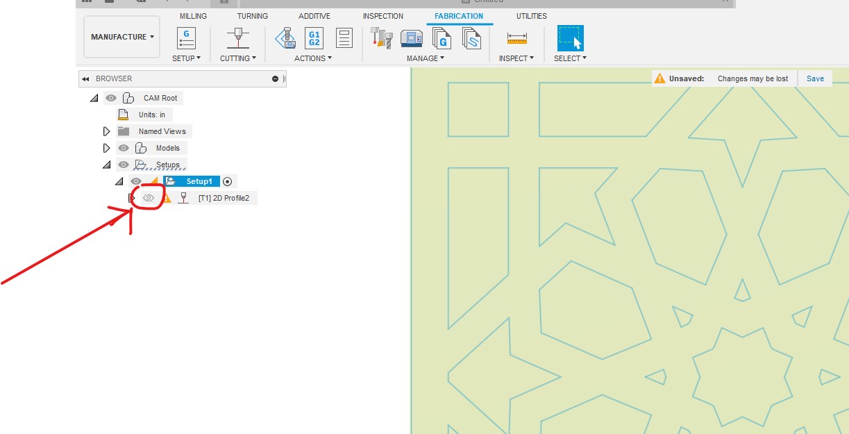
you must click and have the eye show marked when you try to create Gcode.
Don’t cut because you won’t be happy. I don’t have time to look at everything now but if not resolved when i get back from the easter egg hunt i can explain how to fix if someone else don’t
I tried what you said on my file (extruded a sold and used that to generate g-code) and it didn’t work. I downloaded and uploaded your file and changed from hypertherm to razorweld and it won’t generate g-code. It still gives the linking constraints error.
I reloaded your original file and try to run the simulator on it, and it wont’ run.
nope…it took me maybe 2 mins tops to just go back to design and extrude. You must be cutting thicker metal if running at 40 ipm. I like to so my lead-in down a little so if speed is 80ipm i do 60ipm for lead-in speed. Just something to consider if you’re not already doing this with cuts. Start off with book settings and dial it in is the best thing. GL and post some pics
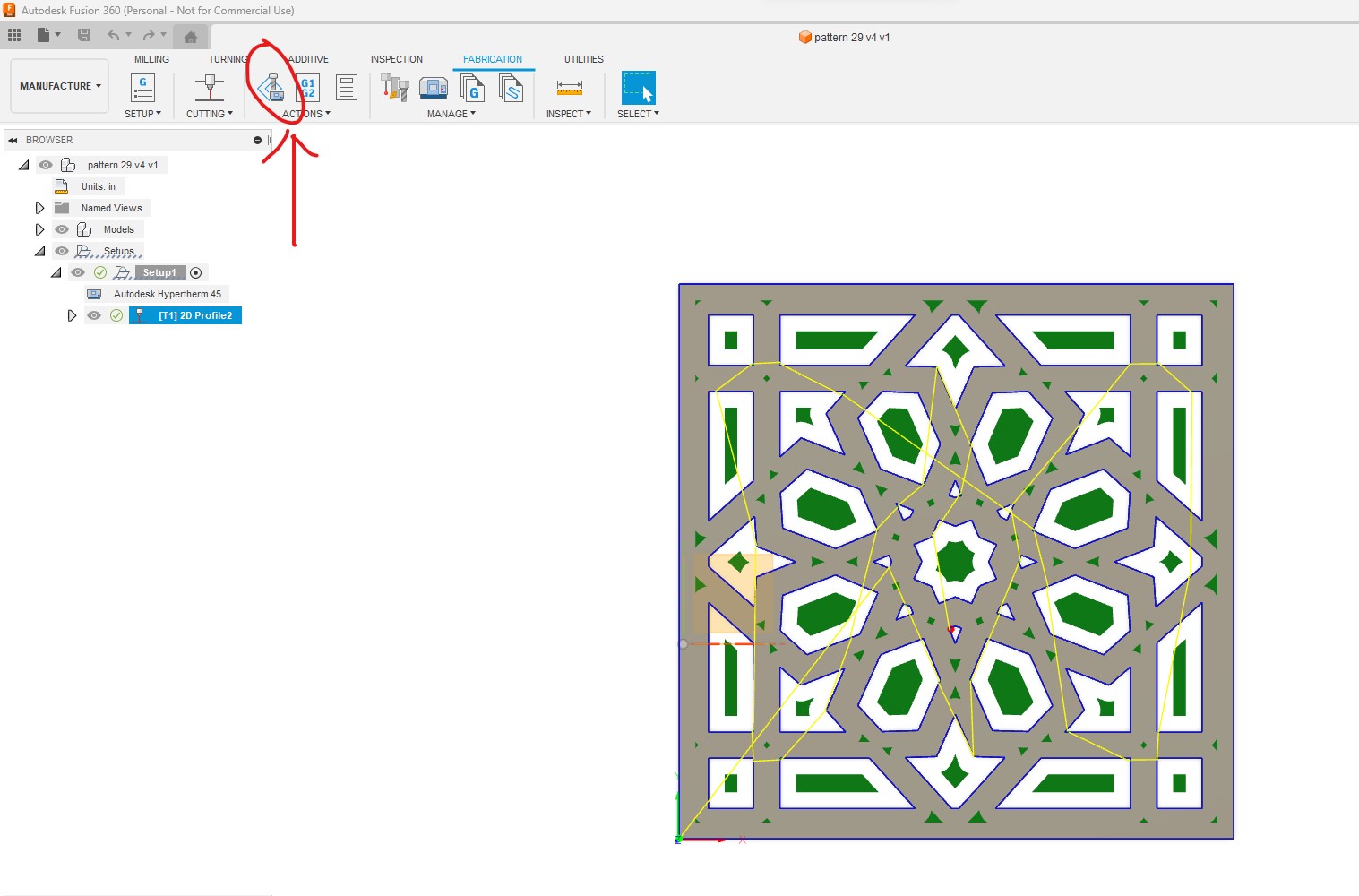
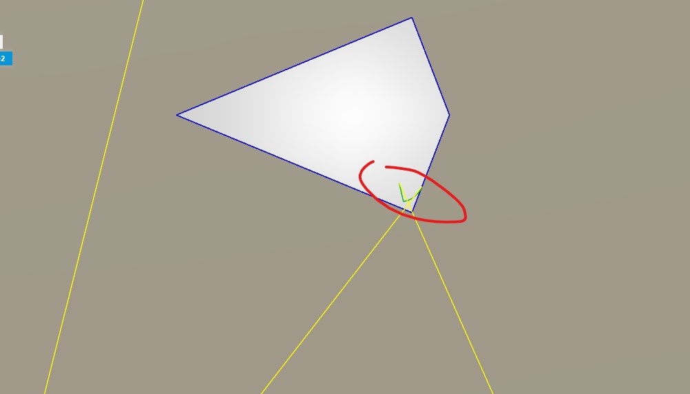
Now, when I generate the g-code. I’m getting this error - and I never screw with that tab in the cutting tool. I’m guessing it’s okay to run.
Warning: From the highest Z position of the stock, the Safe Distance (Linking tab) is higher than the specified Retract Height (Heights tab). To maintain the Safe Distance, the Retract Height as been raised. If you want to maintain a lower Retract Height, consider reducing the Safe Distance.
Sounds like you removed the lead-in and pierce clearance but I might remove lead-in but leave the clearance alone. i didn’t have to do that on my computer so you might have something else not right. Never seen that error before. i’m sure someone will answer you.
That error, relating to z-axis is not related to the piercing clearance.
Piercing Clearance lets you specify a distance away from the part profile to safely pierce the material, before starting the contour. This value is in addition to the Lead In distance values.
Consider this more like a tool moving in laterally like a milling machine. It is not in the z-axis plunging motion but a lateral motion of the table.
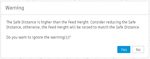
This is what Autodesk says about your current error:
“The Safe Distance is higher than the Feed Height.” when calculating a toolpath in Fusion 360
Autodesk Support
Mar 24, 2022
“The Safe Distance is higher than the Feed Height.” when calculating a toolpath in Fusion 360:
A yellow warning sign is placed next to the toolpath operation .
The Linking tab of the toolpath operation form shows a red value for Safe Distance .
Causes:
The value calculated for Safe Distance is higher than the value for Feed Height which normally has a default height of 5mm.
For example :
The value in the maximum roughing stepdown gets automatically added to the safe distance. If the default safe distance value is 1mm. Anything above a 5mm stepdown results in a warning.
Solution:
To avoid the warning message choose one of the following measures:
Increase the value for the Feed Height until the value for the Safe Distance is shown in black..
Decrease the value for the Safe Distance until the corresponding field shows the value in black.