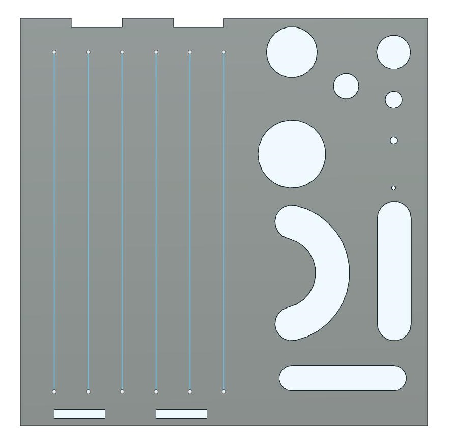
Here’s something I came up with to nail down the settings of my plasma machine on varying thicknesses of metal. This is perfect for testing different travel speeds (using the five straight lines) and seeing how much pierce delay you need. Also a good way to see if the head is out of tram and cutting angled.
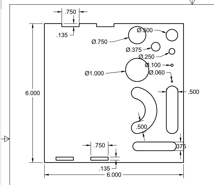
You’ll find an image of the DXF, the DXF itself, and a dimensioned drawing to compare with your cut part to figure out how close your machine is running to tolerance.
Depending on how things are set up, you may have to put the six lines in a separate sketch. When you go to make a profile for cutting, Run them with a center computer compensation, and do a separate cut profile for each line with a different feedrate. Vary by 5 or 10ipm, and watch how dross forms or disappears as a result. The contours can be ran at any speed you chose, but I recommend you run all the non-straight lines at the same speed to see how the machine handles those different shapes.
testcuts.dxf (7.9 KB)