I’m sure it’s covered somewhere, but I didn’t know what to search to find it.
How do you set up stitch cuts for bends in Fusion? I have the outline in, but … how do you tell it to just run a straight line??
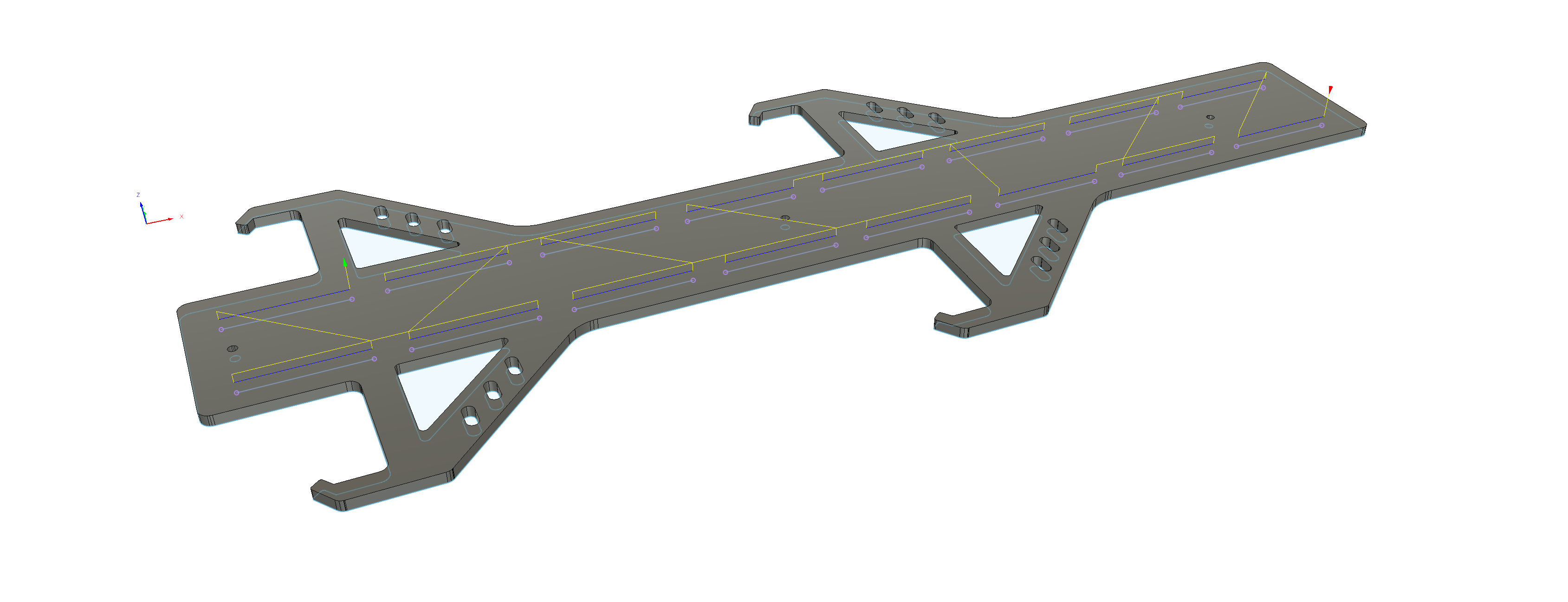
jack stand storage rack v1.f3d (512.3 KB)
I’m sure it’s covered somewhere, but I didn’t know what to search to find it.
How do you set up stitch cuts for bends in Fusion? I have the outline in, but … how do you tell it to just run a straight line??
jack stand storage rack v1.f3d (512.3 KB)
Let’s look at your scenario at about 8:15am-8:20am pst on the live stream
BUT!..
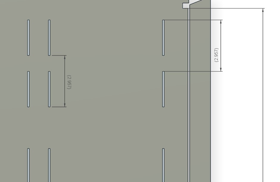
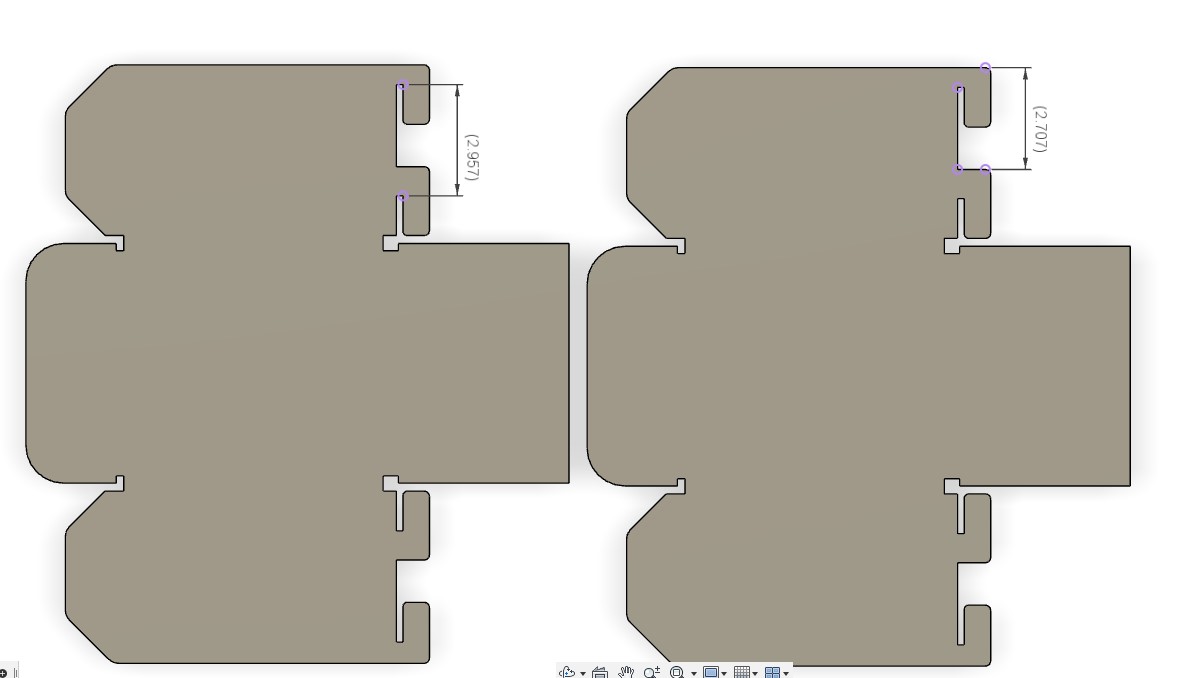
if you plan on using 1/4" material a single line bend relief will crash before reaching 90 degrees because of where the neutral axis is in relationship to the cross section of the plate.
a slot is required to achieved a 90 degree bend with this method.
Here is a another video of why you need a slot and how the K factor (bend allowance) plays a role in the minimum width of the slot.
in this example the k factor is .4 and the thickness is .25.
.4*.25= .1
.1*2= .2
the minimum slot width should be .2 to complete a 90 degree bend.( this will still crash some, it is the absolute minimum for best result always make a test bend, measure, and reapply a good result to your program)
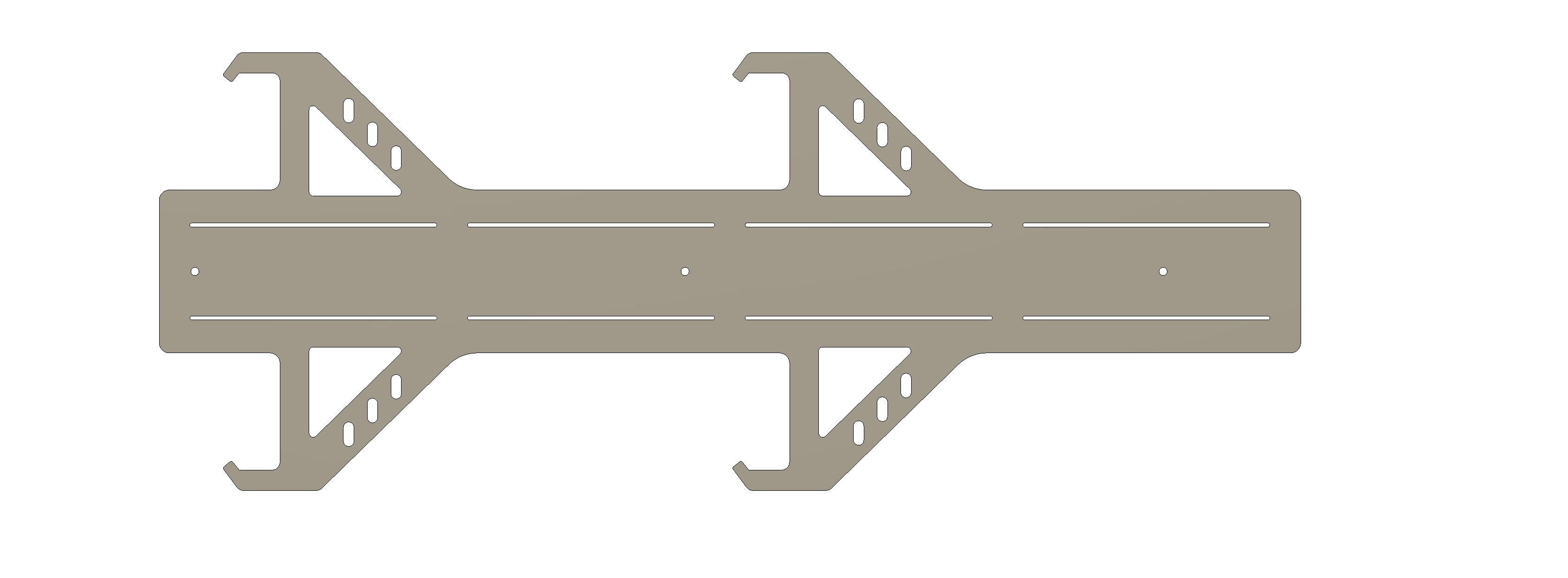
jack stand storage rack v1 (1) tin slot mod.f3d (896.8 KB)
**(also I explain the k factor the difference between the amount of material above and below the neutral axis . I mean the small distance between the neutral axis edge vs the entire thickness)b
Thanks so much. That was very, very helpful. I’m not running it 1/4". that’s just what I always extrude to before going into manufacturing. It’s going to be 14 gauge. I hadn’t realized you could set up two cutting paths and generate them into one g-code file.
you are welcome
The same slot rule applies but relative to 14 ga a single line kerf is a slot.
14ga = .075
.075*.4 = .03
.03*2 = .06 ( about kerf )
it is very handy, you can also pattern tool paths or add pauses all of which can be added to one program.
The math for the minimum slot is actually a little different I’ll post exactly what it is but it’s a little bigger than the metal thickness. ( I’ll make some adjustments above to the text)
Of course this morning I was working on 60° slots so I had it on the brain.
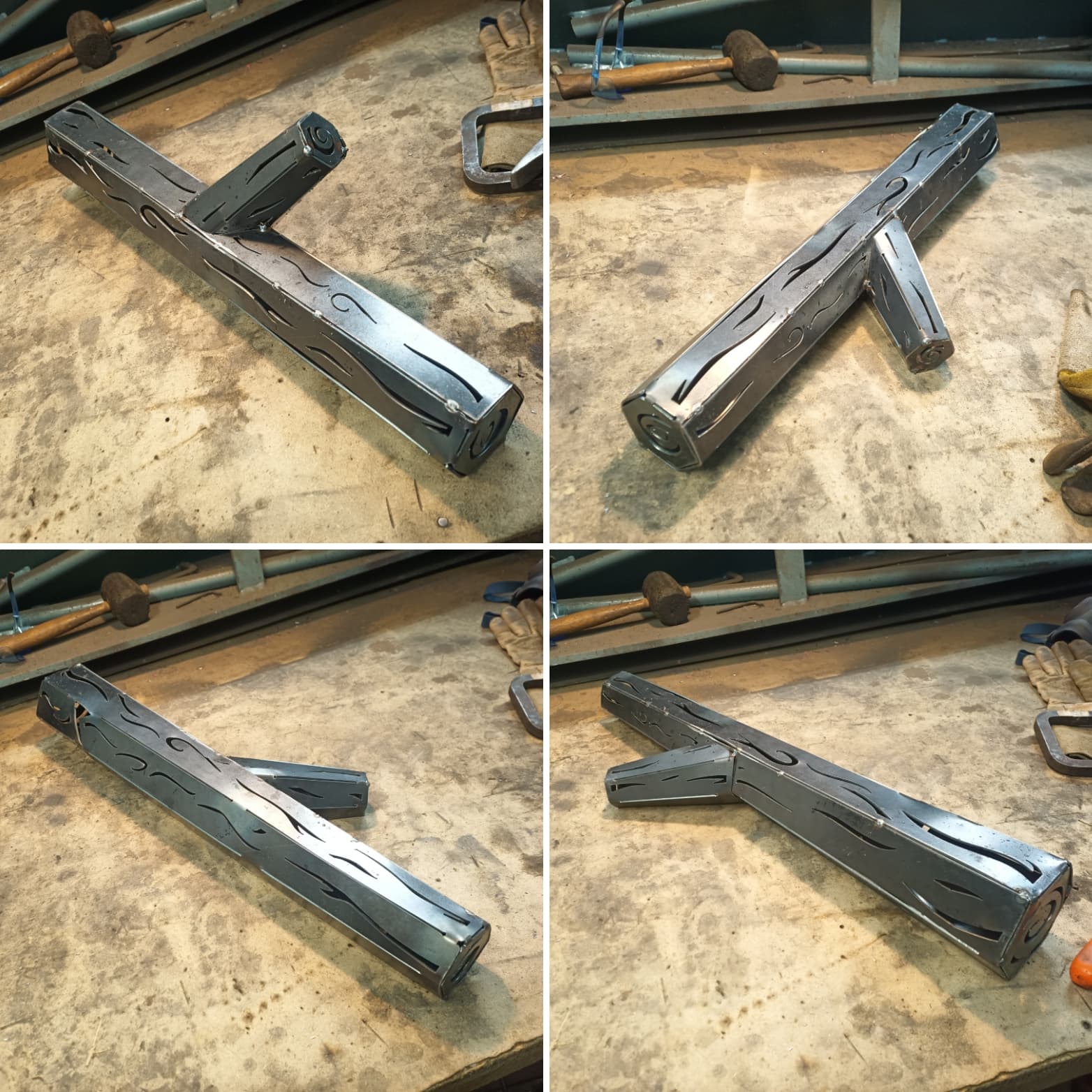
This metal log I made for my next fire pit submission is only two parts.
A Truncated Hexacone Wye
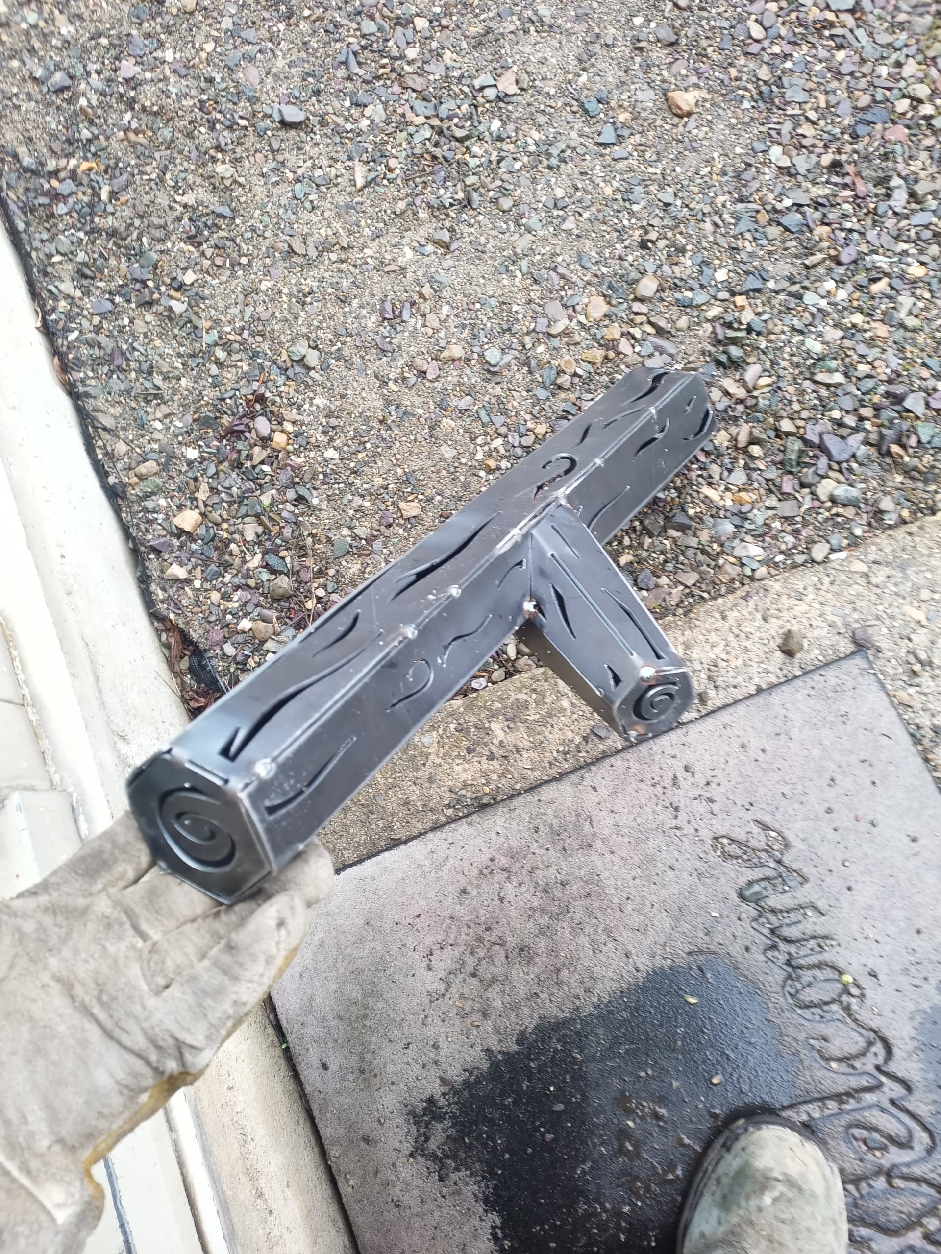
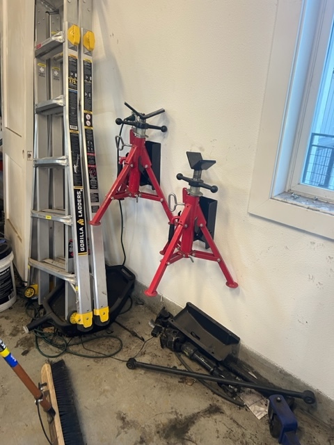
Here’s the finished product. sorry, picture didn’t come out very well.
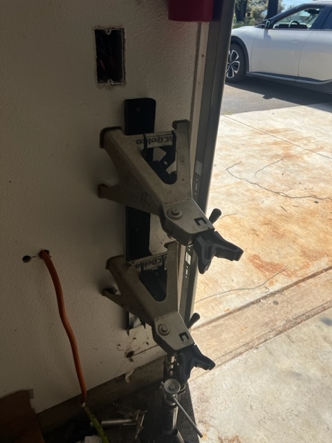
Also scaled it down and made a bracket for a smaller jackstand.
Next is to design brackets to hold the pipe stands, which are much bigger and much more awkward.
I love how quickly you put this into service. Necessity is the mother…
Nice design!
My jack stand centers would fall out if they were tilting down a little [cheap jack stands - probably HF] so I might add this strap where the lower feet would touch.
I just made it smaller over all and shortened the size of the ‘mouth’ to fix that problem.
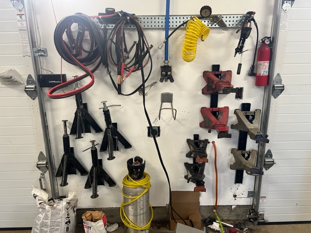
when i get home later I’ll share a project i started few months ago and got side tracked on another project. Basically a workshop pegboard that you screw to the wall. The really cool part about doing a pegboard design is once you get the right end attachment to pegboard you can add anything to the face. The pegboard i’m working on is about 90% completed with screws to the wall with 16" centers. Sorry I know this isn’t helping but made me think of that design. It might help you come up with way of attaching your bracket to the wall.

I wanted a few things I ‘learned’. It doesn’t automatically including all the cutting elements in the g-code, you have to go back and select the setup to get all the cutting elements included. And, for some reasons I selected my RazorWeld different ways for each cutting element and then it complained I was asking for a tool change. So I had to make sure I selected them exactly the same each time.
You just need to make sure that that the tool in each tool path is the same one. Otherwise, Fusion expects us to have the profession license.
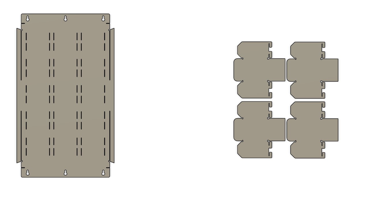
Workshop wall shelf with bins.dxf (2.6 MB)
So started on this a few months ago and never finished everything. You have board and bins in this DXF. Whats so cool about this is any tool or item you just need to add the hook from the bins. you can copy and drag them to another item, and it will hook on this board. if bigger item you just need to have the spacing correct and it will hook on. I guess I didn’t get to making my wall mounts 16" center for putting up the studs. you can see there are some bends but should be easy enough to bend if using like 16ga steel. That when i’ll add to fileshare when i make a bunch of cool attachments for my dewalt tools
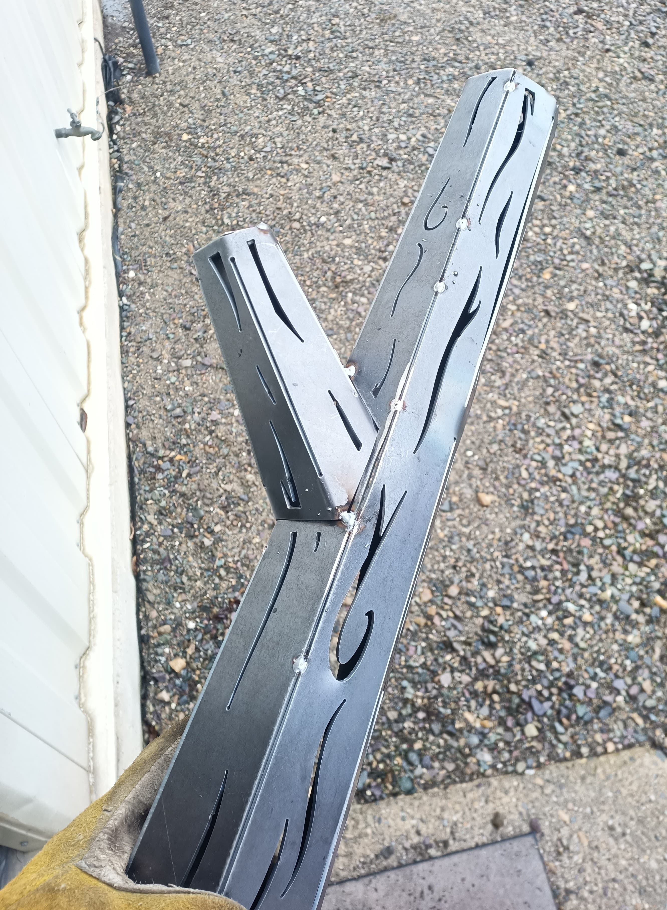
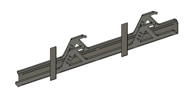
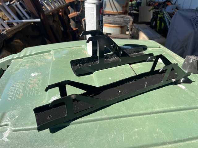
Here’s a better pictures of the brackets. I’m continuing to modify it for smaller jack stands and larger triangle based screw jack stands (the single).
I absolutely love to make/design brackets!!! They are so functional and nearly impossible to buy one that fits ones particular need.
Agreed 100%. Well done