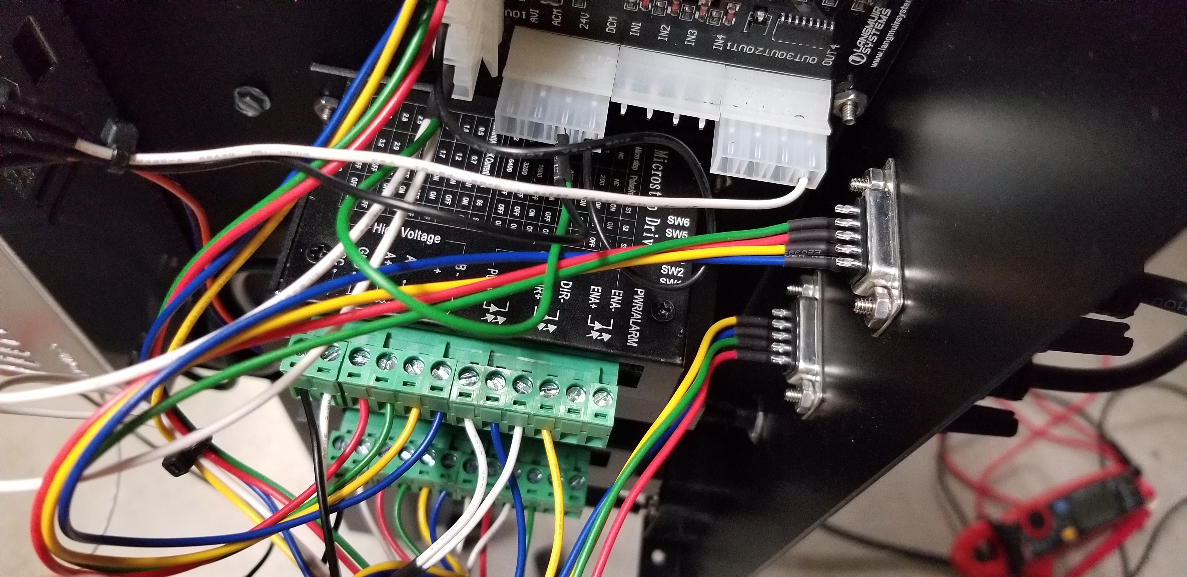
I’m having issue with my x axis stepper not having any force behind it (stalls when i pinch the coupler with my fingers when not connected to screw). I noticed that the wire colors are the same for both the x and y axis as wired to each stepper, but the go to different pins on the connector.
Y axis
A+, red to pin 8 stepper
A-, green to pin 9
B+, yellow to pin7
B-, blue to pin6
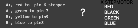
X axis
       A+, red to  pin 6 stepper
       A-, green to pin 7
       B+, yellow to pin9
       B-, blue to pin8
If the stepper doesn’t have much power, but IS stepping smoothly when unloaded, then it may be insufficient current. This COULD be caused by accidentally flipping the switches that control current on the X Stepper driver. I noticed that X & Y are different when I installed my controller, but didn’t record the specific switch settings. It makes sense that they would be different and, IIRC, the Y was set for 4Amps and X set for 3Amps. I could be wrong about the specifics on the X axis, but, even at 3A you would not be able to stall the motor by holding the coupler with your fingers - you might rip the skin off your fingers if you tried.
Another alternative could be the number of microsteps per step. These should both be set to 32.
Sorry, i forgot to mention that i took the stepper apart and put it back together and it started working fine. Maybe it was binding inside the stepper case. Not sure, and not confident on the fix, but it’s working fine.
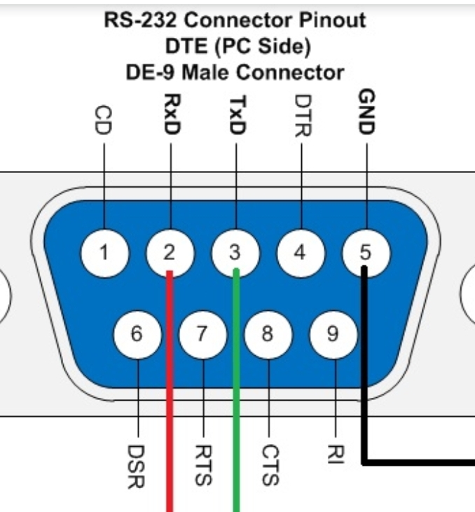
Hi.I have a OG CrossFire, my X stepmotor DB9 connector has been damage (gone) , I want to splice and replace it by a regular old computer , the wires from the motor, blue, black, red green… were to they go red, green, blue, yellow…
Anyone can help…
Thanks
I’m not sure I understand this comment. Do you mean that you have an old cable with a DB9 connector that you want to use to replace the original stepper motor connector?
Ok, look at the very first post in this thread. It has a photo and description of how the 4 wires from the motor get wired to the connector. You can use you meter to determine which of your new cable wires are connected to pins 6 through 9 and that should tell you where the motor wires should go.
Ok, you threw me off talking about your ‘computer’, I assumed it was a cable you were repurposing.
In any case, using your multimeter, I think you will find that the motor wires, RED & BLUE go to one winding, BLK and GRN go to the other. The OHMMETER mode will read low resistance across a winding, and open between the two windings to confirm this.
I would hook it up:
BLU - A+
RED - A-
BLK - B+
GRN - B-
and try it with a small move, the motor should turn, but MAY go in the wrong direction, if it goes in the wrong direction then reverse the BLK & GRN wires. This may not be as originally wired, but your system will operate correctly.