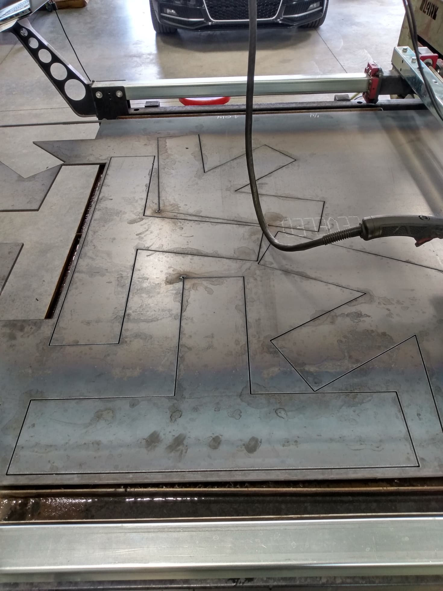
Hey all. Ive been struggling with this machine since I got it, but havent posted as I have been trying to figure it out myself. first off, I cant seem to get it to cut to size with any repeatability. If I do a 16 gauge 4" circle, its pretty close. Larger pieces are almost always under size O.D. and inside shapes are almost always too small I.D. For instance, I cut this headache rack infill. well, its a 1/16th under size, and the inside slots are about 1/16" too small. Its supposed to be 16 3/8" and the slots 2 1/4" wide. If i were to adjust the kerf width, I would be going the wrong way with one of them. The machine is a hypertherm 45. The material is 10 gauge. Running it at 45 amp with 123 for speed. I have tried the 129 recommended with no real difference. I tried slowing it down to see if it helped and it didnt. Almost new consumables. It still does this even when I change them. Also, the X axis does not cut straight. I think the tube might have a twist to it? It always does it the same amount and in the same spot.


I don’t know what this does in Fusion but this feature might be an answer. Perhaps @TinWhisperer could explain this feature.
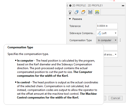
I am thinking the “In control” may allow you to alter both compensations for inside and outside cuts with different numbers. I am actually thinking I need to figure this out as well. Thanks for posing this topic.
“In computer” has to be chosen for Firecontrol.
“In control” allows the machine deal with the kerf width. Firecontrol can not do this.
Only even select " In Computer" when running FireControl
have you check it with a straight edge yet?
I wonder if the torch cable is pulling the torch out of alignment during the cut ?
unfortunately not. I have tried following the cut by manually swinging the torch cable as it cuts. It didnt help, and its always in the same location on the X axis. whether im all of the way positive on the Y axis, or way down at the bottom. Yes i tried putting a straight edge on it. Its pretty darn straight. Thats why I’m wondering if there is a twist. Like the gantry swings one way and then another following a twist. I watched the servo motors while it cuts across the X, and they do not move at all, so its not a programming thing.
can the x axis be flip end for end ? then you could see if it mirrors your result.
I dont think so. The holes for the lead screw mounts wouldnt be right.
update on this. I ordered a new X axis tube, and got it installed today. The cuts are 90% better. I noticed the tube had a slight bend in it before I even installed it, but its much better and tolerable for now.
I have not found a fix for it cutting under size yet though. Its only long distances. I cut some truss plates with the new cross tube, and the 5" legs for the plates are dead on, but any long distance like 20" or more, it cuts under size. I dont think its accurately measuring distance. Not sure what I could do about that other than try to add a little to the size of the pieces in CAD.

Are you setting it to cut on the outside of the line?
I know this is a long shot but @brownfox taught me to clamp the material to the table: remove all variables that you can. You are showing that you are off just shy of a 1/16 of an inch.
Is it possible that with all of the vibration/movement of the gantry that the sheet could move?
Sort of like the nap of the carpet and the movement of a rug on top of a rug. It generally always moves the same direction. That vibration and the slats may be working in a similar fashion.
Another rabbit hole:
You say that the measurement that is longer than 20 inches will be under-sized.
Attach a rigid pointer/pin to the torch. Align a very accurate ruler (secure with tape or clamps).
- Move the torch exactly 6 inches with FireControl, verify the movement by referencing to the pointer/pin to the ruler. Keep mentally tracking the overall movement. Repeat across the entire table.
- What you are looking for is there an incremental creep or is there an area of the table where you see consistent lags.
Theory:
-
You find an area where the lag occurs. Perhaps the lead screw had a thread that was manufactured with an “error/blip”. Perhaps this is an area of the gantry movement where combined forces of the torch and bearings all add more torque to slow the motor movement.
-
It is a gradual creep. Again, manufacturing error of the lead screw or a worn Delrin traveling nut (more likely scenario). Obviously, the gradual creep would be easier to fix: replace the Delrin nut or the lead screw or put in a not-so-complicated fudge of the dimension with a simple multiply by the factor of, lets say “1.002604”
I actually calculated that number:
Since you are off by 1/16 of an inch in 24 inches. And there are (384) 1/16ths of an inch in the 24 inches. That is an error/factor of 1/384. 1 divided by 384 gives us 0.002604.
But I might try clamping the material to the table first.
I taught you that? I don’t even clamp my own stuff to the table. I do hold down the occasional workpiece if I see deflection, but clamping it sounds hard. But it depends on what it is.
For the OP, what is your kerf set at, book specs?
Keep in mind as consumables wear, the kerf will increase, however slight.
Also, per the specs on Langmuirs website…
Motion accuracy is 0.002” per 12” inches. So you’re within spec anyway. But I feel your pain on the lack of a straight cut. I should try replacing my x axis as well.
Wouldn’t be the first time that I quoted the wrong person or misinterpreted what was implied.
Well, it is best we quash this rumor about your clamping skills else you will be asked by other users. ![]()
I have tried different kerf’s. as I posted in the beginning, If I increase the Kerf, than the inside cuts are far too small. setting it about .010 larger than book seems to help a little without making the inside shapes too much too small.
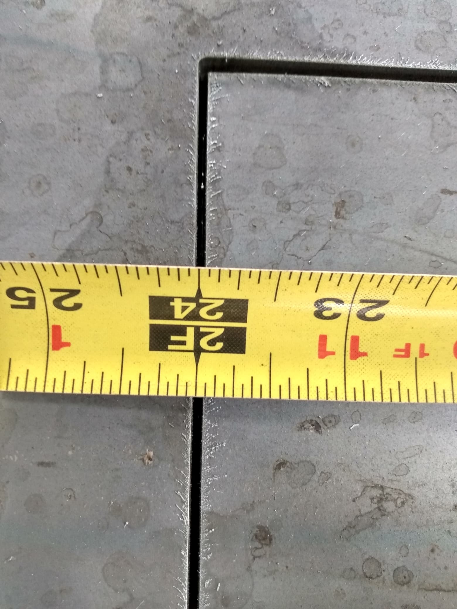
Yes. Notice, my tape measure. the smaller measurements are real close. Its only when there is longer shapes where it starts shrinking. The picture’s with the tape measure are the T plate. the width of the T’s are great. Just not the overall length.
this what actually what I planned on doing next. Just havent had a chance.
I think this is an error that scales to the size of the object. Meaning that the error is there on the smaller sizes, but as you say, they are “real close” as in too small to really notice. It should be possible for you to scale up a design in Fusion after you finish it but before post processing to account for your machine’s tendencies. 1/16th of an inch over 24 inches would be a scale factor of 0.0026 if my math is right. It might be worth a try before doing anything more drastic to the machine. I’m not familiar enough with all the software to know if there is a way to make the scaling process automatic if this is the problem.
Good luck with this!
Edit: The error of 1/16th per 24 inches is 0.0026, the actual scale factor to correct for the error would actually be 1.0026 I think. Someone more mathematically inclined double check that for me!
I just asked what you had your kerf set at. Kerf width is not something where you just “try different ones”.
Run a small shape without an offset and measure the result. However much smaller than your intended shape, is your kerf width.
Already did. Yesterday! See above.