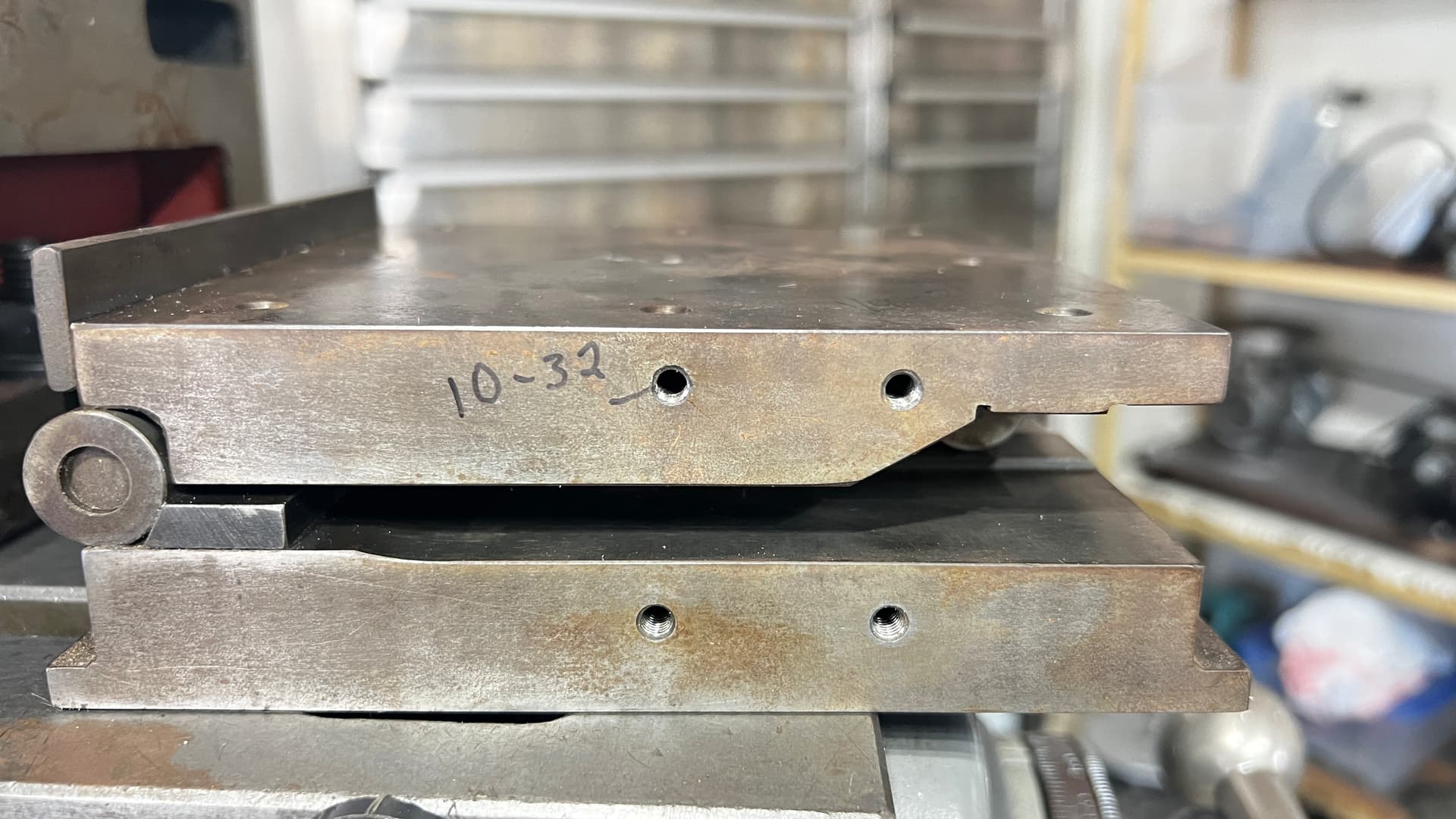
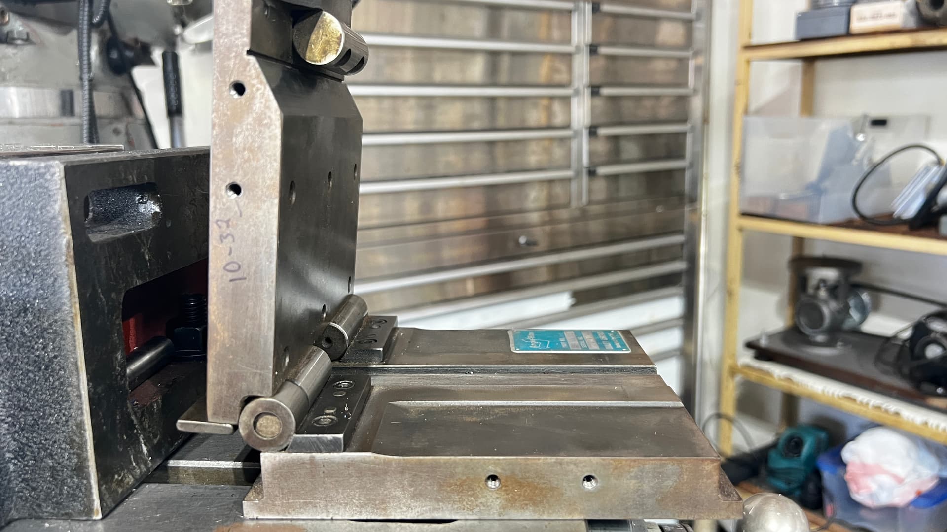
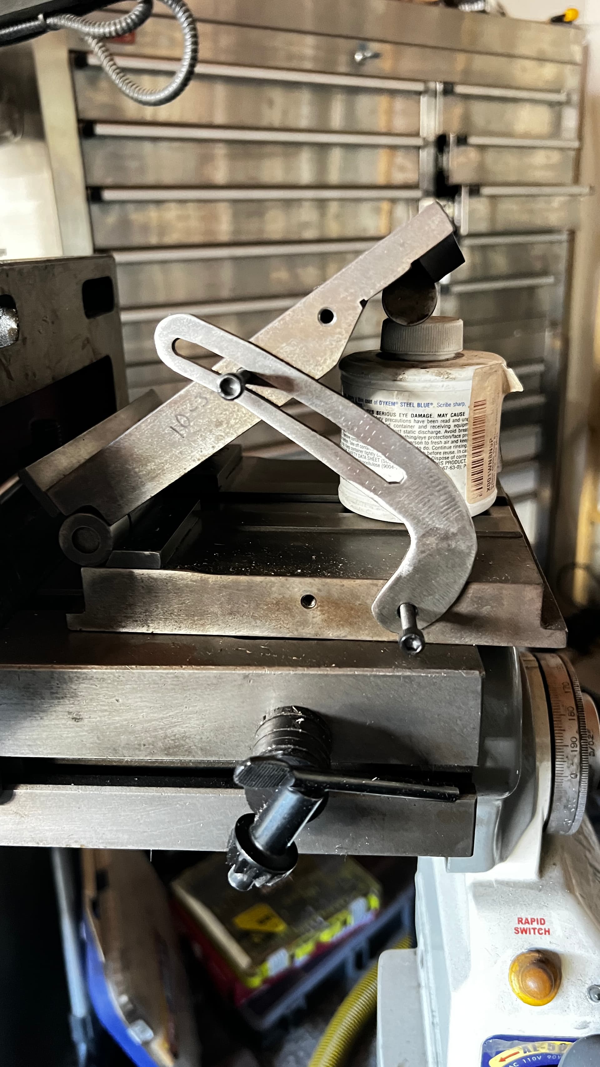
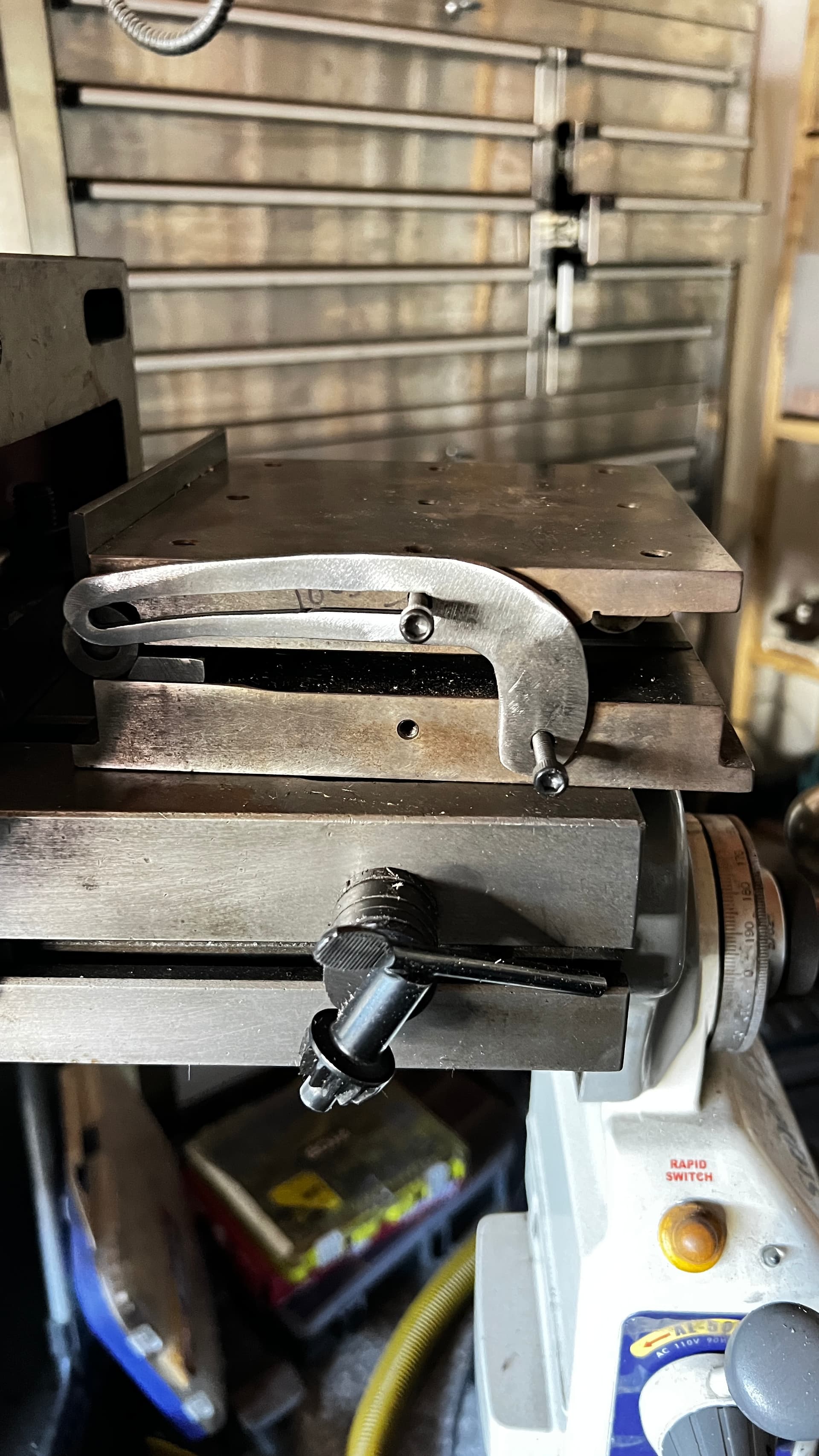
I picked up a 5" sine plate but the locking strap is missing. I have no clue how to design one to cut out. (Dimensions, arc angle etc. Don’t have one to copy. Scoured the inter webs. Brain hurts. any thoughts?
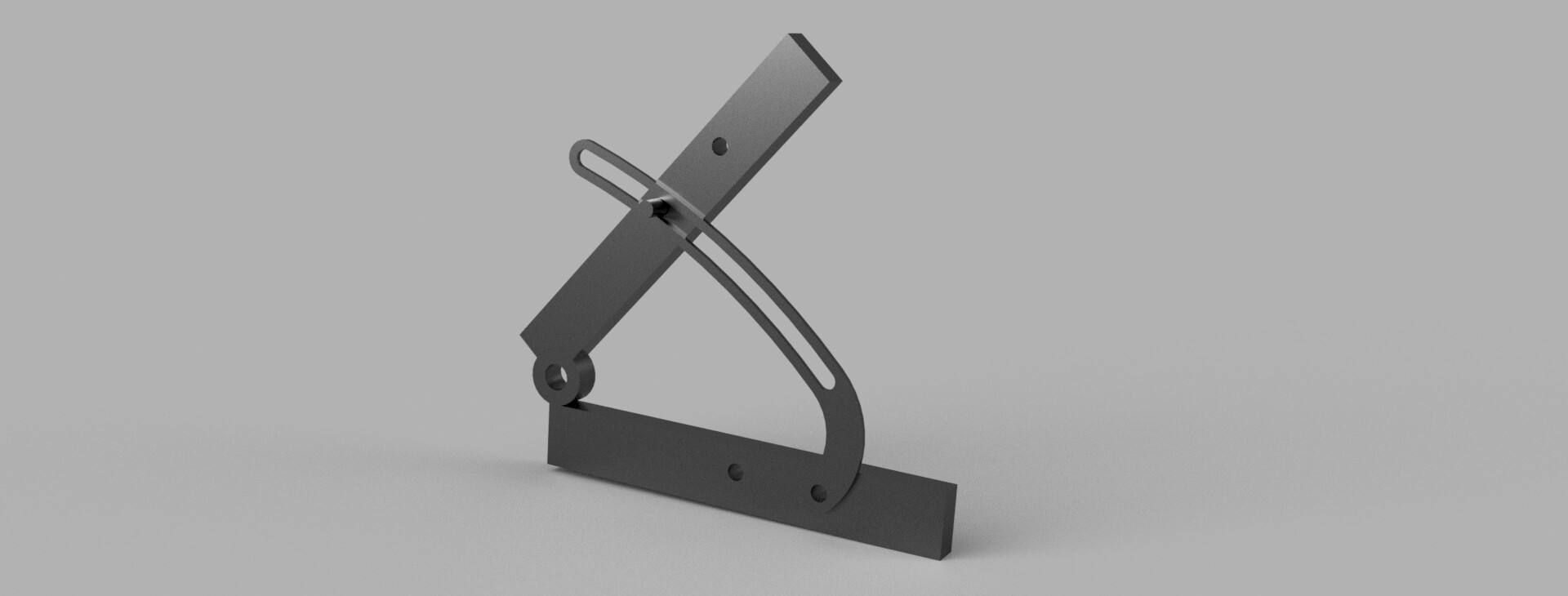
So you mean something like this:
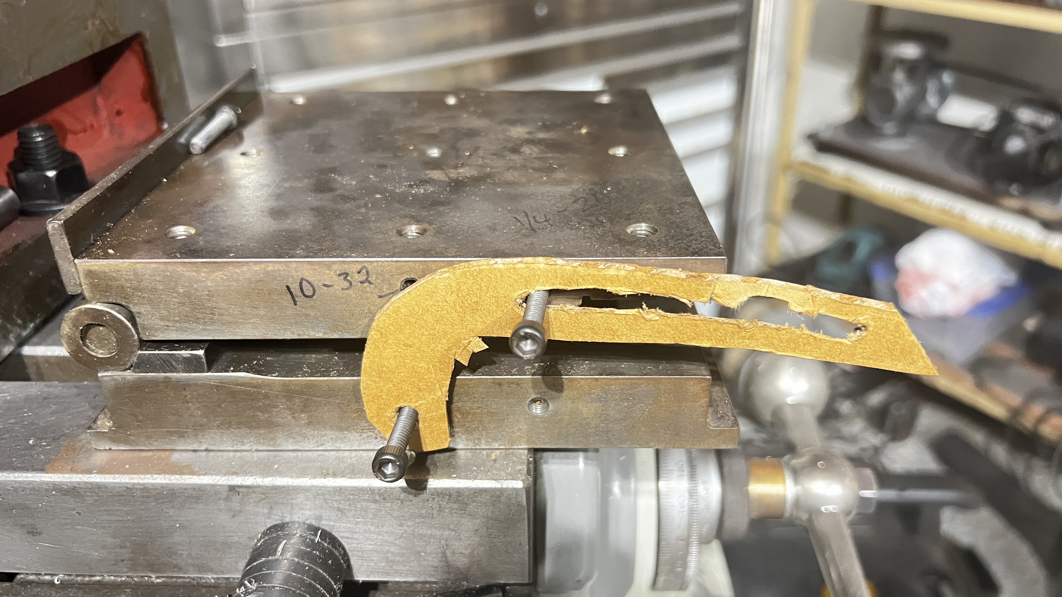
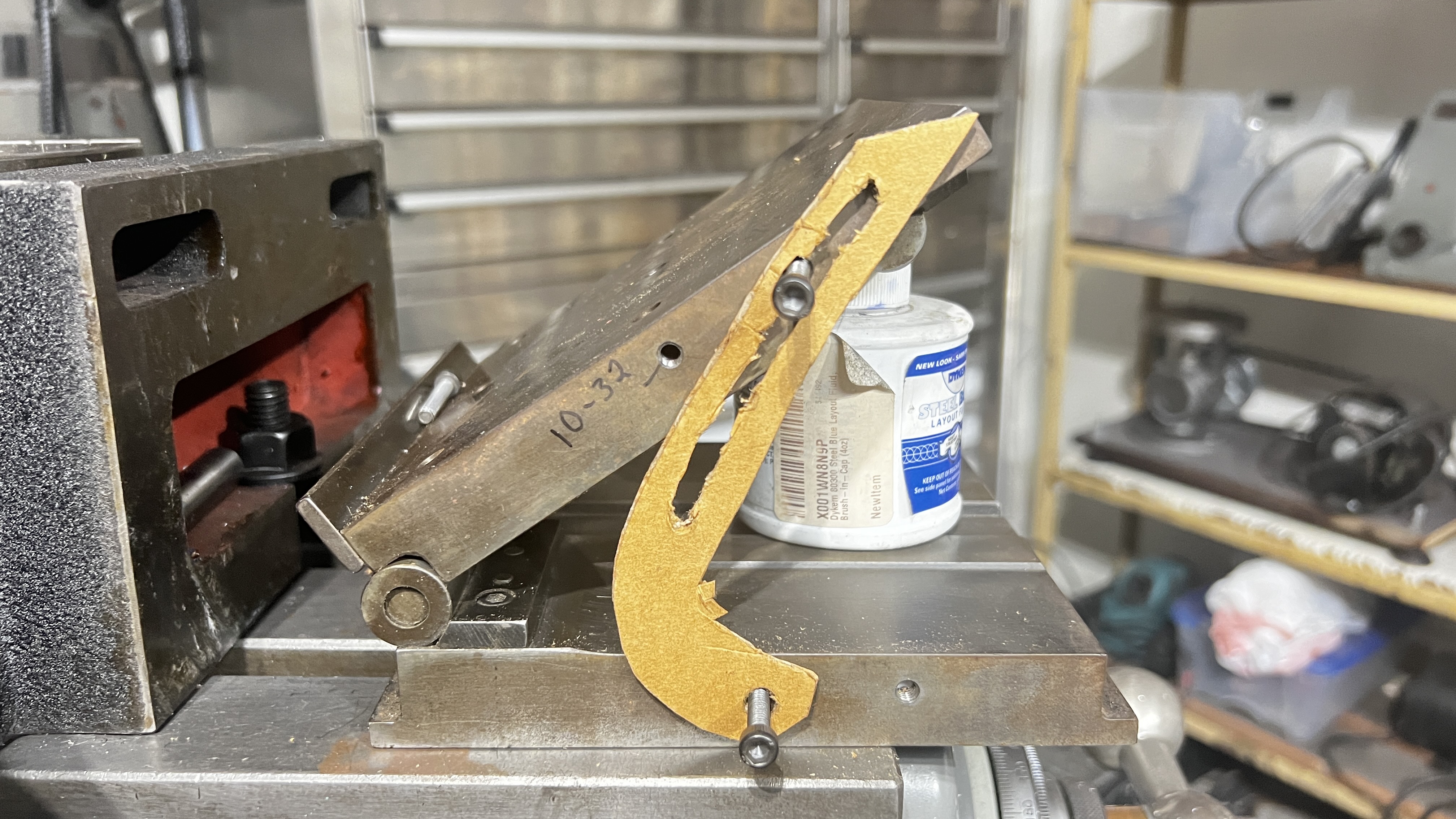
You need to make the black bracket? I am old school: you could mock up a test sample with stiff paper like a manila folder.
Can you list the dimensions?
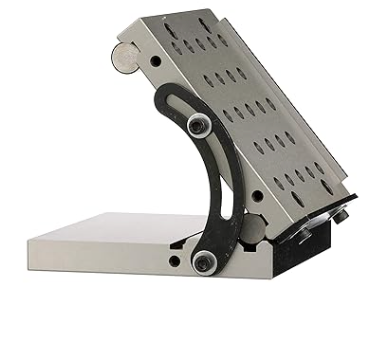
In you cad program, draw the side view with the plate in three or four positions. Use the centers of the bracket connections to place an arc. Then use the the offset tool to expand the bracket from its attachment points. Two offset lines both directions from the arc: one for the slot and one for the outside of the bracket. Two of the points need to be the fully open and the fully closed position.
Never mind: That doesn’t work like I thought:
I see what you mean. I have seen a demonstration of how @TinWhisperer will make a 3D part and then attach with restricted movement. I hope he will help out with this.
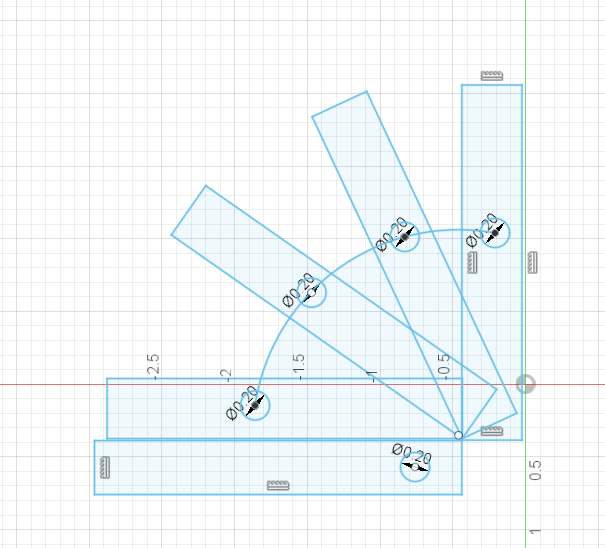
On second thought, I just copied that arc and moved it in place, this might be close. Not sure:
2 Likes
Thanks. The more I think about it, the distance from the pivot point to the bolt hole is 4.25" I drew a circle then extruded one quarter of it and I’m 3D printing now. Would need refinement of course… See how it goes.
1 Like
Well the quarter idea was bad… ![]()
1 Like
Yours looks like it might follow my original idea. Get a measurement there in the closed, one fully open. Make an arc to satisfy both and the midpoints are not really that important unless you need to have the bracket not rise above the plate surface.
I don’t know what those are used for. Sorry. I am assuming machining or positioning devices.
Put the side of that thing on a flatbed scanner with a ruler beside it and post the picture on here . It will save the hassle of the human error that comes with taking the measurements. Then using a calibrated canvas tool infusion 360 you should be able to make a very close representation of the part you want. @ChelanJim posted a lot of good information to chew on.
2 Likes
scan.pdf (288.8 KB)
1 Like
Perfect exactly what we wanted. A live stream of video tomorrow morning using this PDF to go through the motions to create a replacement bracket.
1 Like
Oh man. Now I won’t sleep tonight. ![]()
This Morning let work through @SwoD project of recreating a Sine Plate locking strap.
We will use the scan(2D flatbed) that @SwoD provided as the basis to the drawing.
Also we ll review a F3D @ChelanJim send me of this project.
I am not a machinist and never used or touch one of these so I’ll be make a lot of assumptions about this component.
Live Stream Channels
We ll start around 500am mst
Here is the files from the video
Sine Plate Locking Strap Forum Example v2.f3d (1.6 MB)
sine plate locking strap TW.dxf (3.0 KB)
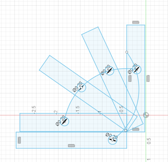
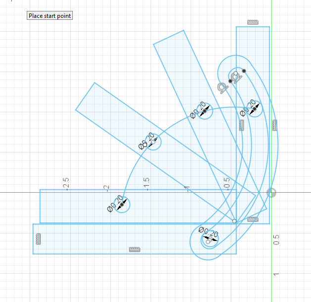
I tried a couple different straps in the model. Hopeful you get something from this video. I fumbled around some with the joints buut managed to get the model to preform how i wanted.
5 Likes
Very useful! Loved the tangential relationship with the pin.
You were very kind with your assessment of my joint assembly. Thanks. ![]()
That took me hours to get to that point and by then I had fussed with that block to constrain/fix it to that plate 3 different times. Lots of more learning!
Thank you @SwoD for bringing this project to the forum. I believe all 3 of us initially approached it as a very straight forward matter and then the “hurting ones head” started to kick in.
As always, thank you Tin for your time and willingness to help us learn. ![]() I wish there was a tip jar! Well, maybe I don’t really wish for a tip jar.
I wish there was a tip jar! Well, maybe I don’t really wish for a tip jar. ![]()
![]()
1 Like
1 Like
I know it’s so fun and sometimes frustrating to learn Fusion but the little shots of dopamine when a light bulb goes off keep you going. Thanks for your effort with my project! ![]()
2 Likes
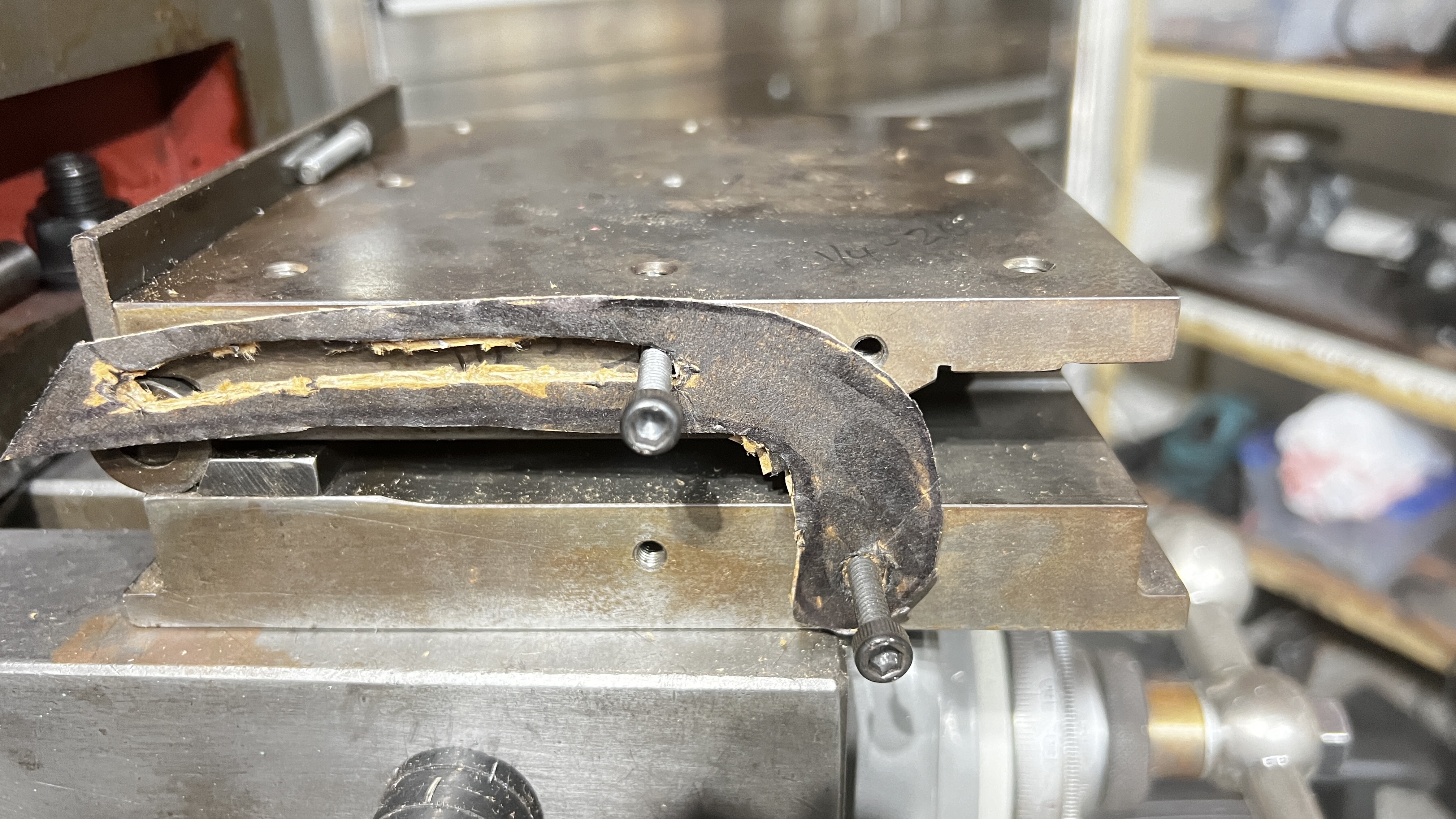
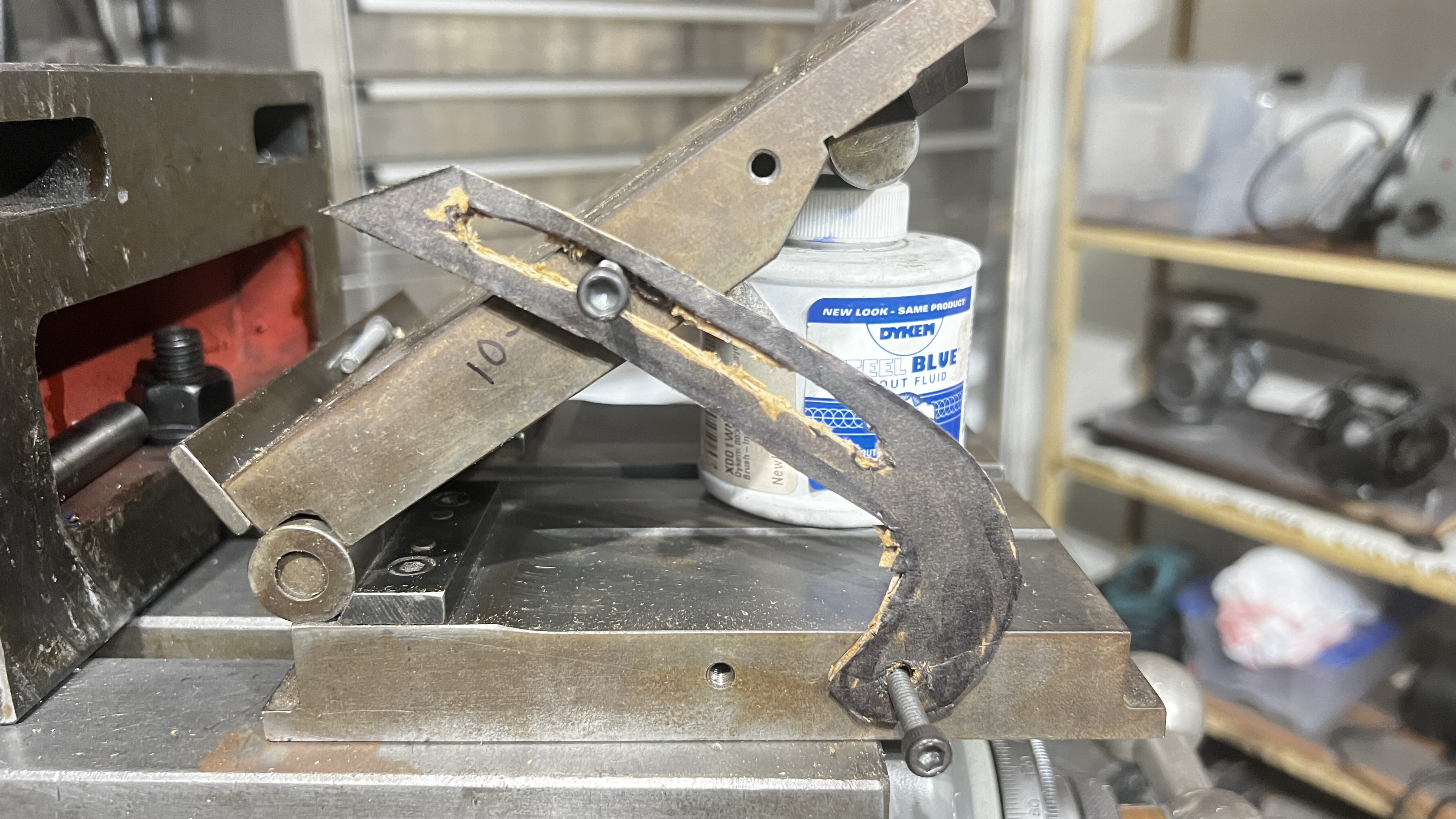
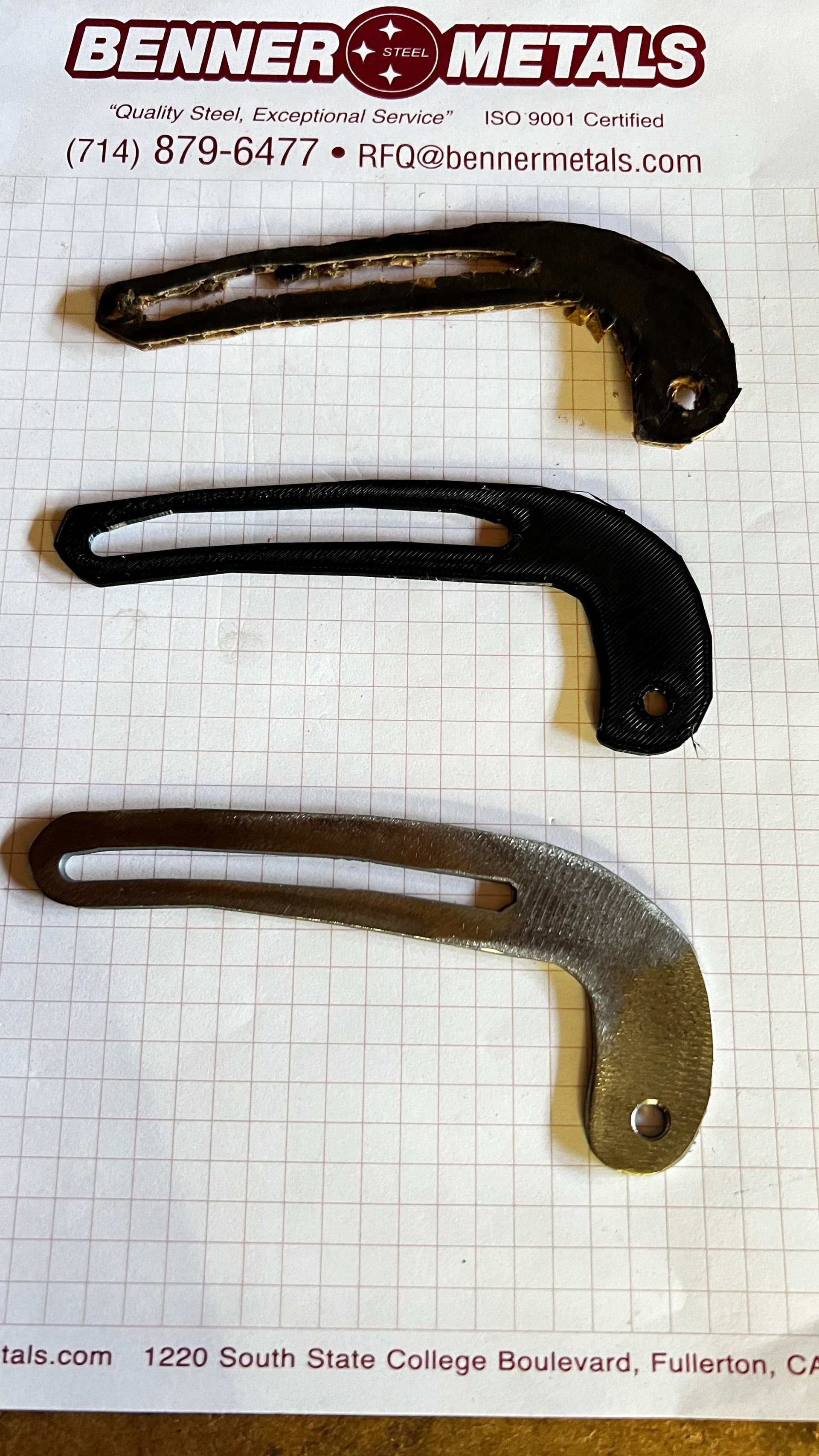
Thanks Mr. Tin. Can of oil for you!!! Fun watching your posted video as I’m a little green with Fusion. So much to absorb but rewarding when you get it. I went from cardboard to 3D print to finally, plasma cut, tweaking a little at a time. I imported my first cardboard mock-up to Fusion with mesh, did a tracing sketch to clean and finished the sketch. 3d printed to test, refined a bit more then cut out with the plasma. Unlike suburban tool, my strap too, always rises above the plate surface at some point. Think it’s the mounting hole spacing. Anyhow I will download and cut your worthy examples so thanks once again. Cheers
2 Likes
I need to get the proper hardware so that I’ll be able to tighten up. With mine, I get 50 degrees max. Don’t think I’d ever go beyond that. Never used one. (I cut out of 1/8" steel. ![]()
You could probably get by with a washer, wing nut and a few drops of blue loctite
That’s an idea. Got some socket head bolts and made a couple spacers on the lathe, because that’s fun to do! ![]()
1 Like