If this thread is not new, can anyone please link me to the right answer?
When I assign radius or tangent lead in and lead out, the program takes my setting and applies it the pieces I intend to keep. I can not find a setting that makes it apply arc lead in/out to the refuse pieces.
Change the cut contour method in the operation setup box. If you were selecting inside offset, change it to outside offset or vice versa. The lead-in/lead-out direction is calculated as the waste side of the part automatically. If yours is turning out wrong, that’s because your offset is wrong.
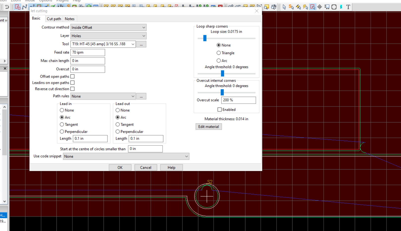
In this part I’m doing both inside & outside offset cuts. The hole is an inside offset where the lead-in/out is inside the circle and thus on the discard side.
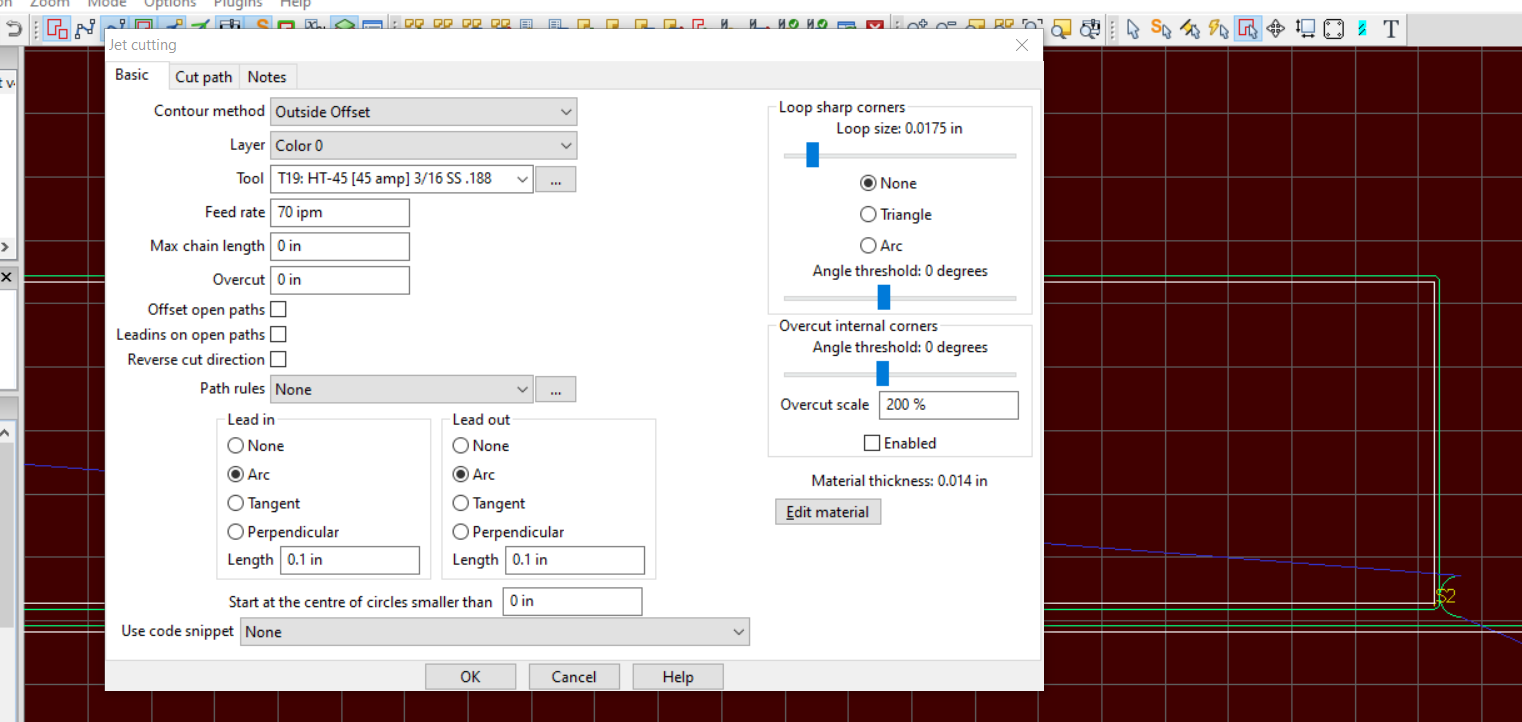
In this part of the project I’m doing an outside cut of the long straight sections. Since it’s outside the line, the lead-in/out is also on the outside which is the waste piece.
Sheetcam automatically assigns Inside/Outside or No Offset to contours based on the drawing. When you import the drawing it should make Outside Offset lines Red, Inside offset lines Yellow and Open lines will be White for No Offset. If it is not selecting the correct offset, there is something wrong with your drawing. Probably open lines somewhere that should be closed.
I learned that it’s also possible in SheetCam to manually assign features to self defined layers (such as Inside, Outside and On Center) and select the appropriate offset for each layer, thereby side stepping the “smart” features in the program and explicitly assigning the pierces to waste locations.
How do you assign assign features to self defined layers. Do you have to break up nested parts first? Still pretty new to sheetcam theres alot to learn.
It’s usually not necessary. If the drawing is good, Sheetcam automatically assigns the correct offsets when you select “outside offset” in your operation.
If you want to move things to another layer, right click on the feature and select “move to layer”. Then select “new layer” and name your new layer.
Once you have things moved to different layers, you can create a jet cutting operation for each layer.
Ok, case in point. I have a drawing imported into sheetcam. Red lines represent outside offset. This is text and should be set as an inside offset. Possibly an issue in the drawing I haven’t addressed yet.
The number of nodes really doesn’t matter, unless they are creating jagged line.
The only way to reduce them without doing more damage, is to manually delete the extra nodes. Inkscape has a “simplify” function, but it almost always leaves a worse result than just leaving the extra nodes.
Looking at your picture it appears that the text is on it’s own layer. In that case you need to set up an ‘inside offset’ cut operation on that layer first.
SheetCam treats layers independently so as far as the cut operation on the text layer is concerned, nothing else exists in the drawing. In SheetCam turn on View->layer tool. You should see a list of layers in your drawing. You can turn individual layers on and off to see what is on each layer.
I had not converted the test to curves in affinity designer and then merged all curves so I assume that why it was treating it as a different layer all together and had it marked as outside offset. Thanks for the comment. I appreciate this community and the fast response times, I hope that once I get more seasoned I can contribute myself.
I use affinity. What you need to do is design the files as one entire object. So once you have your font placed, you basically subtract it from the bottom layer so it’s all one shape.
Edit- you say merged all curves. I don’t think that’s the same way I do it. I’d have to see.
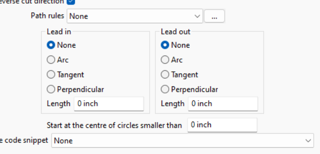
One last thing, what is the difference between these settings in the lead in and lead out section. I normally use none. I have been told to use perpendicular for holes.
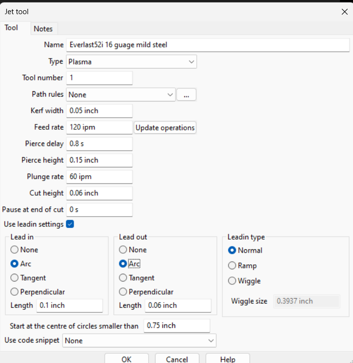
Use an arc lead in/out for everything. I usually use .1 lead in and .06 lead out. This starts and ends the cut in the waste material to prevent having divots from the arc start/stop in your cut lines.
Check that box that says “start at the center of circles smaller than” and put in .75". This will start at the center of the hole and spiral out and around the hole.