I have been cleaning and looking at the gantry design of the Crossfire PRO and am ready to cut the 2" risers hoping they will help in keeping them clean as well as giving needed room under the gantry… but now I am thinking bigger. Why cant I just install 8" risers and weld solid plate in between the plates to stiffen up and counteract inertia. Then, flip the gantry assembly end over end . Unscrew the Z axis and screw it back on upside down, leaving the bearing block as is so it does not run into the X axis bracket. This would leave the Y axis high and dry from debris while the X axis is hanging below it. there would be plenty of room for sealing the gantry from dust and spray which I am finding out once its dry is a nightmare to remove and creates havoc with the bearings and stepper motors. This is of course just a thought at this point and I am looking for anyone that has had similar thoughts. I have spent years in a Machine shop and thinking this way is just ingrained at this point. I hope I explained myself as well as I could. please help…
David DuChene
I think I understand.
The thought that creeps in for me is that ‘increased distance’ will introduce “increased lever arm” and likely forces that will ultimately introduce increased bending, torquing and vibration. That extra movement will increase variations of your cut. I believe your “solution” has the potential of introducing a myriad of “problems.”
I could be wrong. I have been wrong before: Just ask my wife! She has a list just since yesterday.
I started out with the +2" risers off Fireshare, then earlier this year when I trashed my water pan, I made some +4" risers to accommodate a new 3" deep pan and gain a little more Z height since I cut a lot of thick stuff and box tubing.
I was thinking the same thing with stiffeners on each pair of risers, but by the time I got all of them on, the stiffeners were not needed, even with only using one bolt at the top for the Y rails (gained a couple inches of Y travel that way).
I also used .250 plate and milled out the pocket where the bearing block sits to maintain the OE distance for the Y leadscrews.
I think you would cause yourself more problems than you want by inverting the Z asis carriage.
If you are worried about it getting dirty - which really is not a problem, then keep some towels handy and wipe it down when it gets splashed, or after every session.
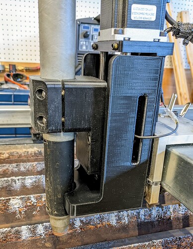
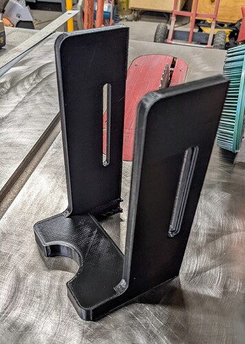
i designed a printed this to protect the Z axis rails from getting junk spalshed onto them. It doesn’t stop everything, but I haven’t had to clean the rails in the 2.5 years since I put it on there.
I like these low profile utilitarian nature of the cover you build there.
This is what it looks like before it’s installed. I just friction fits over the lower plate on the Z axis and you have to feed the IHS wires through the slots. This was printed on my old Ender 3, so the quality is not a nice as the Bambu could do.
Great idea . I am going to design a version for a XR. I stopped using the factory “shield” .
3D printing is amazing . I still cant believe it sometimes.
All these printer now are akin to the dot matrix printers of the past even Bambu.
I have sci fi fantasy level hopes for the future of 3d printing.
@GreatEastern welcome to The forum by the way
Hey ds690, would you be interested in selling one of those to someone that doesn’t own a 3d printer yet, but will someday hopefully? Aka me…
I could probably do that. I can’t guarantee that it will fit right with the Langmuir torch mount, so I’ll probably send you one of my mounts, just in case. Send me a direct message on here or @starrmetalworks on Instagram.

