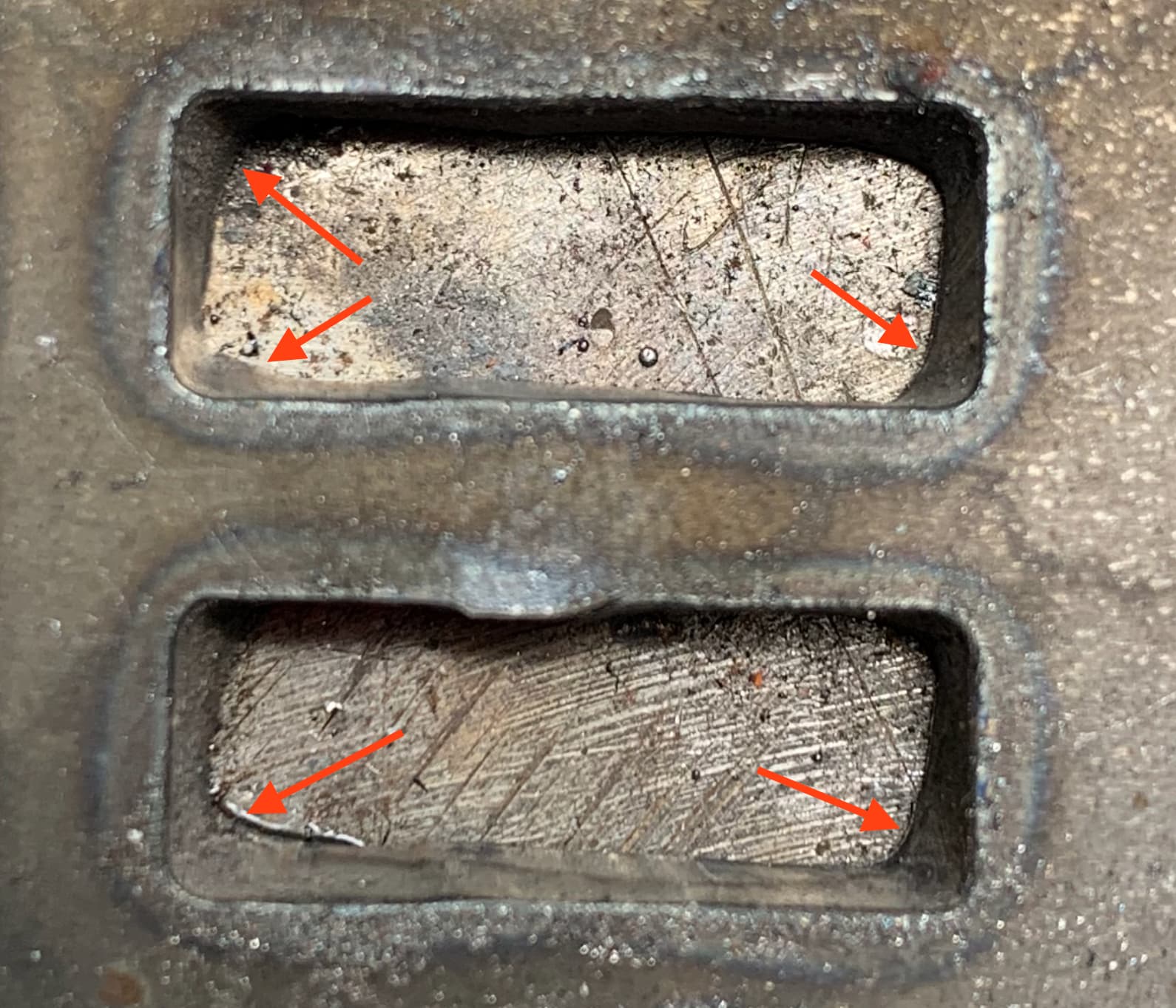
New to this, just set up the table 3-4 weeks ago. I’m working on a prototype for a Belt Grinder using welded slot and tab construction. I’m having trouble with the bottom of .25" slots in .25" material. The top of the slots are within a few hundredth, but the bottom are uneven. In 12 gauge no problem. At the corner angle at the bottom of the slot is much greater for 1/8" or so. Basically I think the bottom of the plasma is trailing and curves around the corner. I’ve tried the following with no success: Feed Optimization slowing down the feed rate .2" before the corners to 30ipm (60%) and 12.5ipm (25%). Lowering the Cut Height to .03. No real difference. Maybe slightly better with the Feed Optimization, but not very noticeable. Any Suggestions?
Second: What kind of Kerf Angle should I expect for a good cut? I’m getting about a 3-4 degree angle in holes. A .5" hole came out .504 on the top and .460 on the bottom.
While laser cutting can be very precise, plasma cutting requires a slightly different approach.
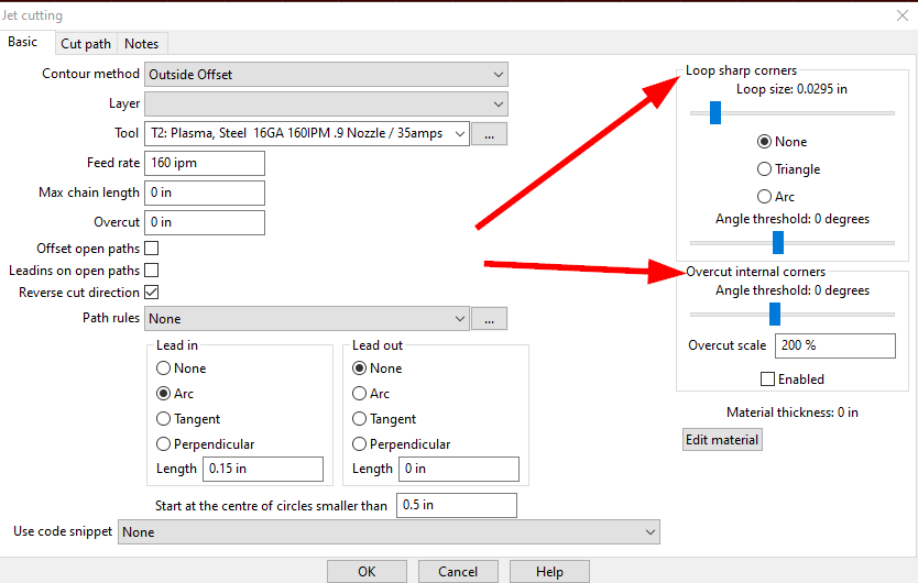
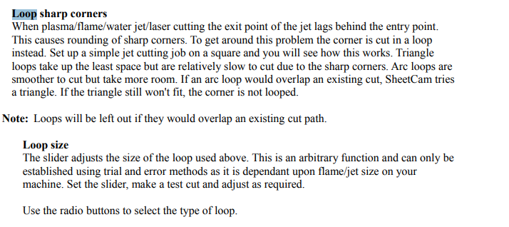
I would design bogbone type of slots so the slot itself it near exactly what you want and the ears to the bogbone allow the plasma to cut outside the rectangle corners. So either design in the dogbones or add them through the plasma post processing options.
That is a good solution, thanks! Easy to do! I’ll do some measurements and try some test “dogbones” I figured there was some tried and true way to do this.
Thanks! Loops are in fusion too, but I believe that in either program they are only on outside corners, not inside corners. May be a way to do something with the dog bone slots and looping the corners, but there’s not much room in those slots…
Thanks @john_s ! Tried the dog bones and they worked very well.
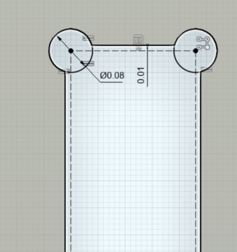
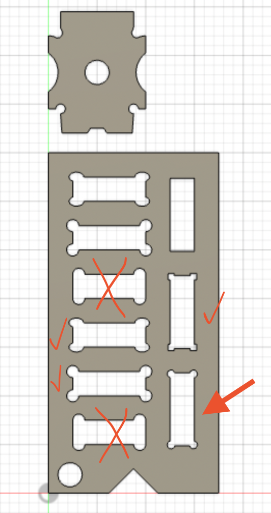
Here’s the test for anyone who is interested. I tried a number of different configurations. I tried circles, ovals, squares and position as the variables. The best was the lower right hand one (pic below). This had small .080 holes in the corner, set .010" inside the edge. Easiest way to do that I found in Fusion is to make a .01" offset in construction mode and make a .080" circle in the corner. Then make equal sized circles in all the corners (Thank you @TinWhisperer for that method from one of your videos). For large arrays of slots I used the rectangular pattern.
5 Different examples. All checked ones worked, but the lower right one had the smallest gaps and was easier to make than the one above it with similar sized but square holes.
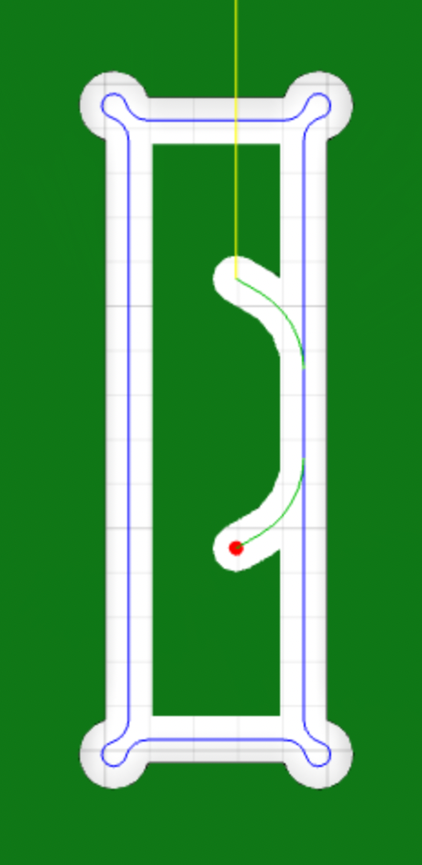
Here’s the tool path. The cutter makes a small loop 45 degreed from the corner. I think this gives the trailing plasma time to catch up doesn’t leave the wider kerf angle.
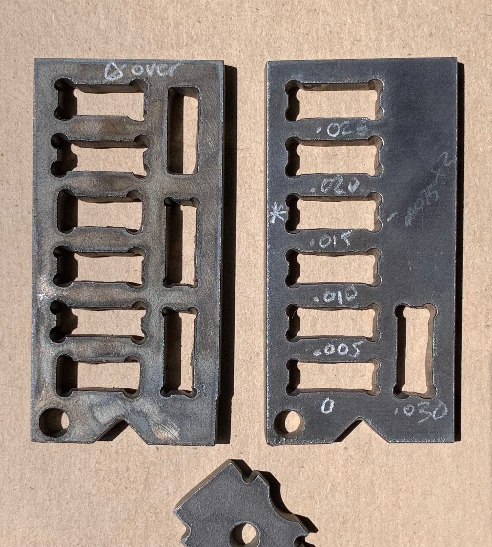
On Left is the test card cut out, the right is a test card with increasing oversized slots to check size of slot. .015" oversize was the smallest that fit a .25" tab.
I’ve been working on the Tab and Slot design recently too. While searching for tips and such, I came across a script for Fusion 360 to help automate creating the Dog Bone. I have no affiliation with the author, just found it useful in my project.