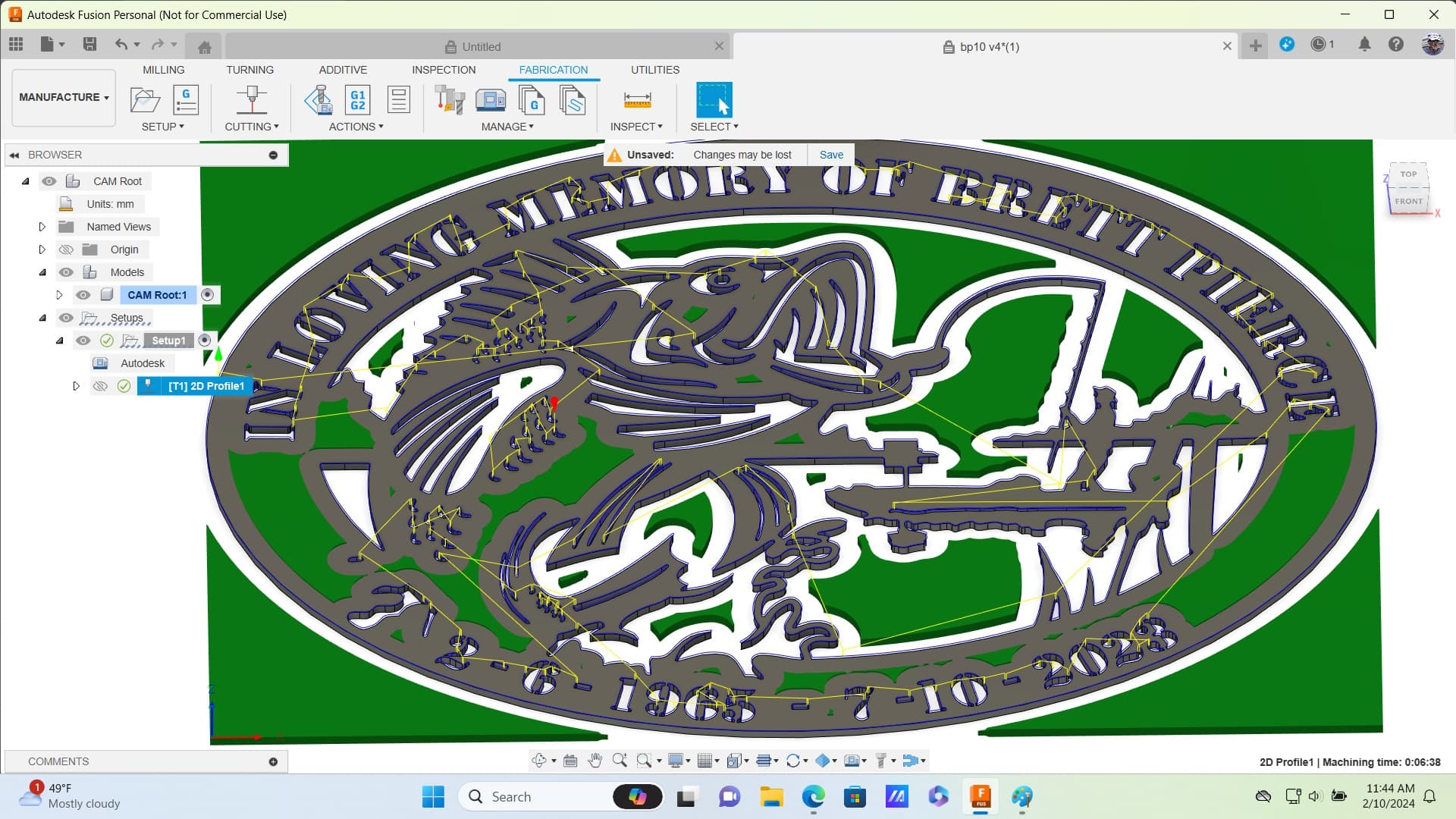
I am trying to make a memorial art project for my sister in law but having a problem at simulation . It runs about half and stops. Says holder collides with stock. Any help would be greatly appreciated. New to all this.
brett2 v5.f3d (1.9 MB)
I noticed no one replied so I’ll dive in.
Judging by the complexity of this thing, I am genuinely surprised you went through and selected 200+ different contours for cutting this thing out however, even as an exclusive Fusion 360 user I have to say that drawing would’ve had me buying and installing Sheetcam.
I saw at the bottom where it mentions running into the holder but I’m wondering if that’s due to the ‘dirtiness’ of the drawing. I mean even the font at the bottom exceeds the outside perimeter.
A failed simulation normally is due to a fault in the drawing itself; delete the construction lines, delete the dotted outlines, clean it up a bit, and if you insist on sticking with Fusion you should definitely make this setup consist of multiple profiles.
This way you can manually select separate areas to disperse the heat of your plasma rather than have mutliple centralized areas receive multiple cuts at once.
Ok thanks. I got raid of that one and started over. Watched some more videos and cleaning up as i go.
Very nice sign…What font are you using? I can do quick video how i would split that upper and lower text in your sign. This will help make it symmetrical.
This is what i have done today , is this better.
bp10 v4.f3d (1.1 MB)
The font is stencil.
When i do setup i get a green check but as sone as i click 2d profile setup shows one or more operations are out-of-date. I don’t know what that is.
That one looks much better on lower numbers. Guess your all set and don’t need video. Check and see if you have any updates in fusion.
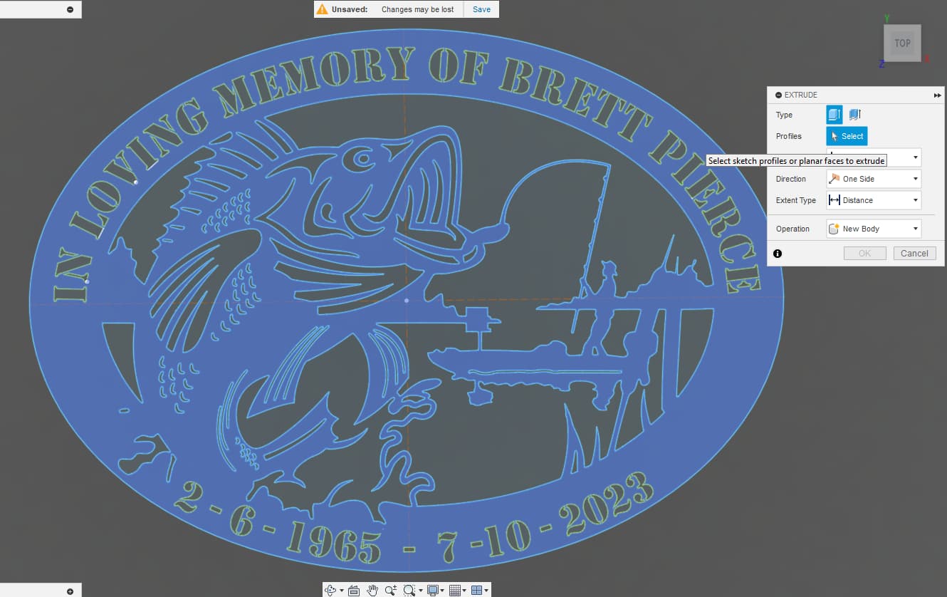
Are you Extruding your Sketch before you leave the Design workspace?
All I did was Extrude, create a Setup, create a Tool Path, got both green check marks for Setup and Tool Path, and the Simulation ran fine and cut all of the details.
2 Likes
in the extrude box what do i have to put in there?
While still in the Design space, press “E” and move mouse over the image. When it lights up you left click:
If you are in a straight on view, you will not see the arrow that you need to grab. Move your image in the 3D world with [Shift] and middle mouse click and move the mouse:
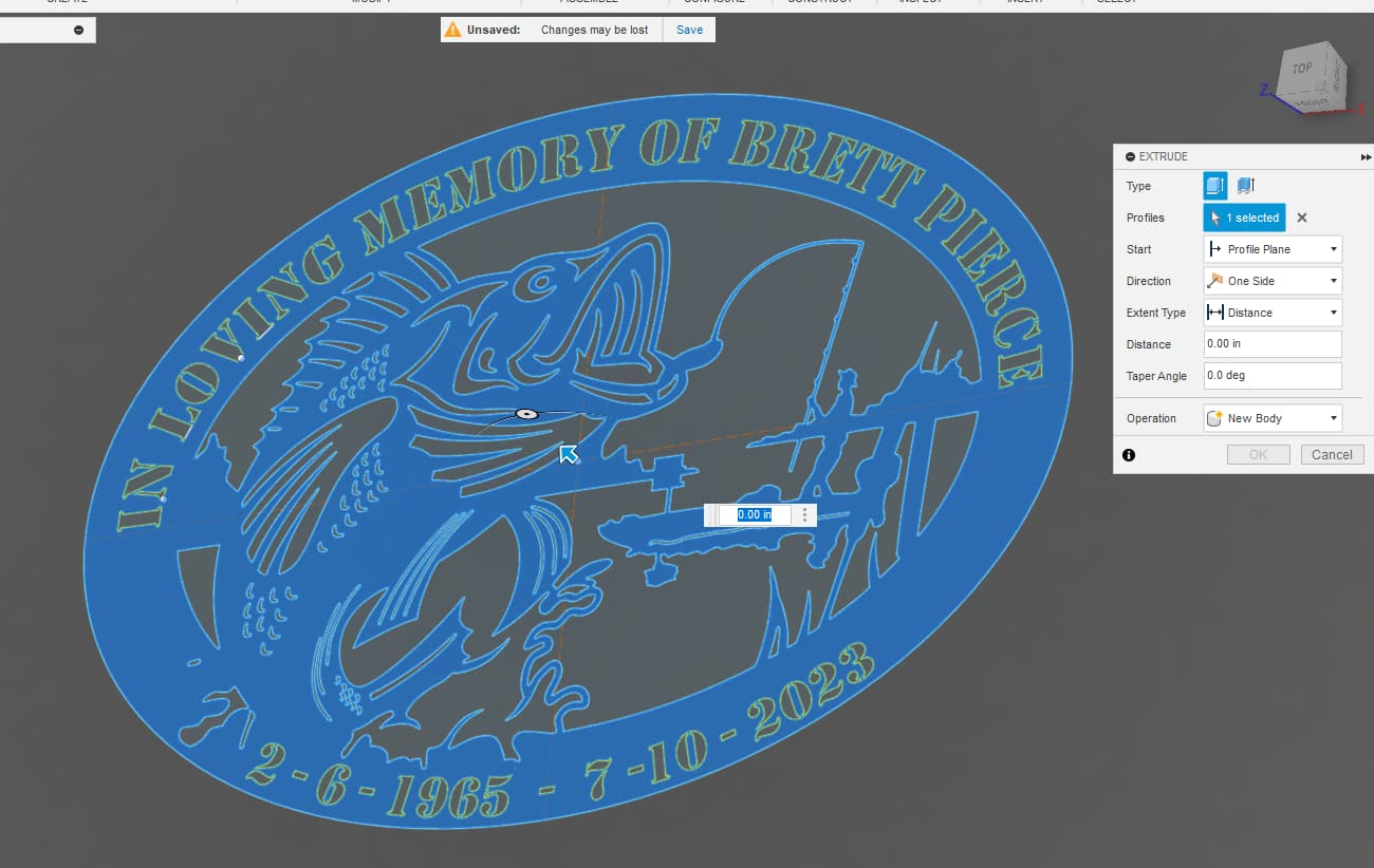
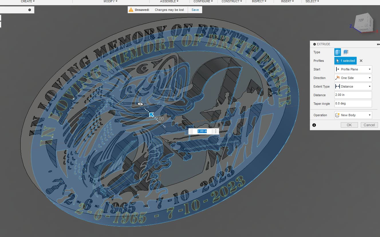
Now you can grab the arrow on the image and move in or out:
You don’t really need to do the above if you want to just type something like the thickness of your metal. You could type any dimension such as 0.125 or .2. You are not going to really use the 3D image for anything other that to use the “face” of the body in Manufacturing. As you get into 3D design, that number will be important.
Most of us just like to see the arrow and move in or out to be sure it is extruding how we expected.
2 Likes
Thank you all very much. This was my first project starting with just a jpeg. It didn’t cut (Simulate) every hole but pretty close. Again thank you all very much.
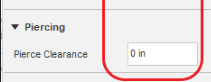
That means your lead-in/lead-out settings would not fit into the contours. Make sure “Pierce Clearance” is set to 0.0. You never need any Pierce clearance, ever. You would reduce them in the linking tab (5th tab) of the toolpath:
Pierce Clearance:
This setting would get most detail:
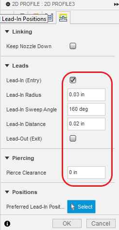
This setting would grab nearly everything:
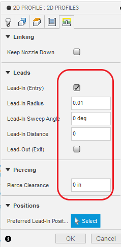
Remove all lead-in/lead-outs and you will grab everything only a smidge larger than the kerf width of your tool.
You lose quality of the cut by decreasing the lead-ins, so there is a compromise there.
2 Likes
Ok thanks will thy that.
I didn’t know you could edit those setting after you ran it once . Learned a lot of new thing in the last 4 day.
1 Like
You want your lead-in to be a 45 or 60 deg angle unless you’re in a narrow area and then use 90 deg. If you use 90 deg the plasma cutter will have to make a sharp turn which can cause marks on your metal. There are many more things like using 20% less speed on lead-in/outs and when to use left compensation and center compensation. These are all good things to look up and watch some YouTube videos.
1 Like
If this is your first project then you’re off to a great start! I was going to tell you earlier that you might want to add some screw holes for hanging it unless you have another plan. Sorry MSU basketball game came ON and everything else stopped.
1 Like
ok thanks. Its like I’m back in school, didn’t think i would be after 40+ years out. A little stressful sometimes , ok mybe a lot. lol
1 Like
You have super knowledgeable folks on this forum. You’ll learn there many different ways to get similar results. Definitely a learning curve to fusion but you’ll never outgrow it. GL and post pics
1 Like