Test the output from the power supply in the electronics enclosure. The DC + and - terminal should be obvious. I think the standard Crossfire uses 24v DC.
If you’re getting low voltage, you can try to turn up the pot to increase the voltage output. It should look like a Phillips head screw near the output terminals.
Yes, @ChelanJim all of that would be on with the control board plugged into the computer via the USB. The control board gets power from the USB. The motors get their power from the power supply.
If you have Windows, you could use the snippet tool.
You can activate it by CTRL SHIFT S
Or perhaps print screen: PrtScn. (You may not see anything happen but go to a photo program and do CTRL V, and it should paste the image.)
It does sound more like what David said: not enough voltage getting to the motors but I would expect some sound. When the power is on, it takes considerable effort to move the shafts of the motors. When the power is off, they move slowly but with only mild resistance.
The power to the motors comes from the DC power supply inside the control box. It is probably a silver box with a bunch of holes in it. There should be screw terminals on one end with AC input and DC output terminals. You need to measure the power output at the DC output terminals.
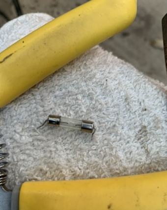
Simple fix. It was indeed the 250v fuse that blew.
After 698 micro screws and getting into the power supply case, the fix was very simple.
Any idea why Langmuir chose to go with a solder-in fuse instead of a removable fuse slot?
Maybe I am the only one that blows them up???
I included a picture of a corner brace for an exterior metal fence that I am working on. It was the first think I cut as soon as the machine was up and running.
Thanks again for everyone’s help. I am sure I will be back here again soon enough. . . .