I should probably add a subtitle, “How to live dangerously and have fun doing it!” so, instead of that, I will add this great big:
WARNING! This topic discusses my modifications to my plasma cutter that involved potentially lethal voltages and currents. It also probably voids whatever meager warranty I had on my plasma cutter. This is NOT a how-to topic or a recommendation of any sort. It is documenting what I have done, fully understanding and accepting the risks. What you do on your own is entirely your responsibility.
Ok, with that made clear, I have already documented mods I made to my CrossFire to add Floating Z axis. Those mods work great and my cutting and consumable life has improved substantially, however one noticeable weakness of relying on Floating Z to calibrate Z height is that it introduces the weight of the Z axis onto the workpiece, potentially deflecting it. This is especially noticeable on thin and warped material. Several solutions have been added by others to deal with this problem, including Proximity Sensors and Ohmic sensors. Without getting into an in-depth analysis of those, I decided that an Ohmic sensor made sense, but researching these I found that add-on Ohmic sensors are expensive and have had reliability issues.
I concluded that the plasma torch is a fairly simple mechanism that should be able to serve as a reliable conductive sensor IF I can get the rest of the Plasma Cutter’s electronics ‘out of the way’ while I’m probing. After a bunch of testing and some amusing and useful collaboration with @Cletus, I came up with a circuit that, during probing:
- Disables the Torch Fire Signal,
- Disconnects the torch’s Pilot Arc wires from the Plasma Cutter electronics and connects it to a simple conductive sense circuit.
- Temporarily connects the other side of the sense circuit to the Work signal.
- Temporarily turns on the Torch Air valve, pushing the electrode away from the tip,
- Opens up the Probe circuit upon contact between the torch tip and the workpiece (via the Work clamp).
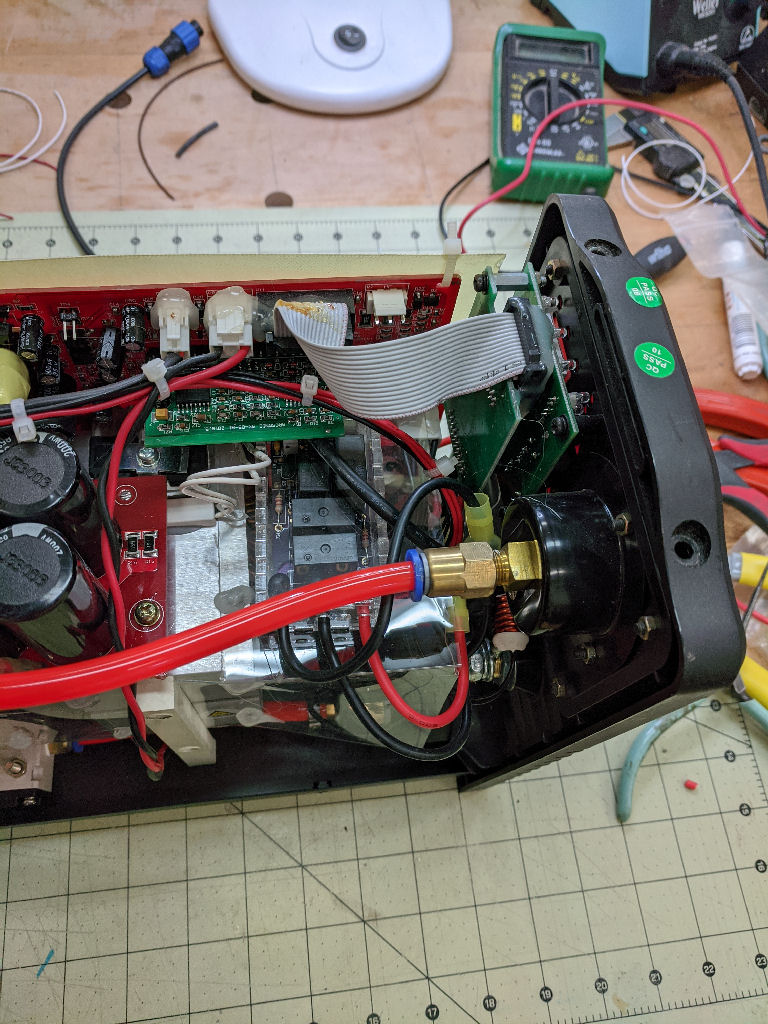
This mod obviously required opening up the Plasma Cutter to decide how this addition could be installed. It also opened up the possibility that I could electrocute myself (SEE WARNING ABOVE!). What I found on my first ‘opening’ was this:

A very nice neat shelf to hold my new circuit!
Ok, that out of the way along with learning how I could ‘break’ into the Plasma Cutter wiring with the least amount of damage, the next thing is to fab the circuit that would go into the PC. So I came up with this:
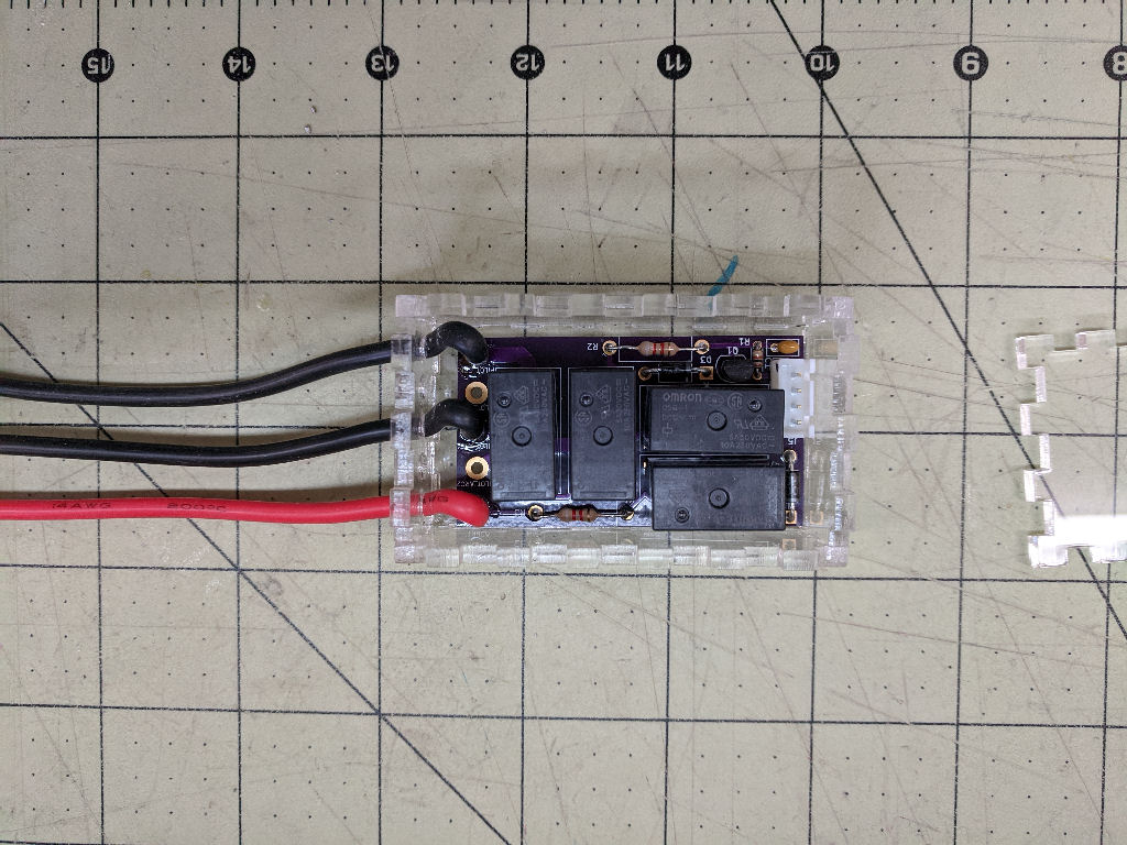

Finally, installing it into the PC, looked like this:
Testing was pretty easy… The first obvious test was to calibrate on a stable workpiece and that came out perfect. But, as I said, the time this really become necessary is with thin material. Looking around my shop I found a piece of copper sheet, about 15mil thick. Hmmm, seemed extreme, but what the heck? So, here is my first test, using the Floating Z probe method:
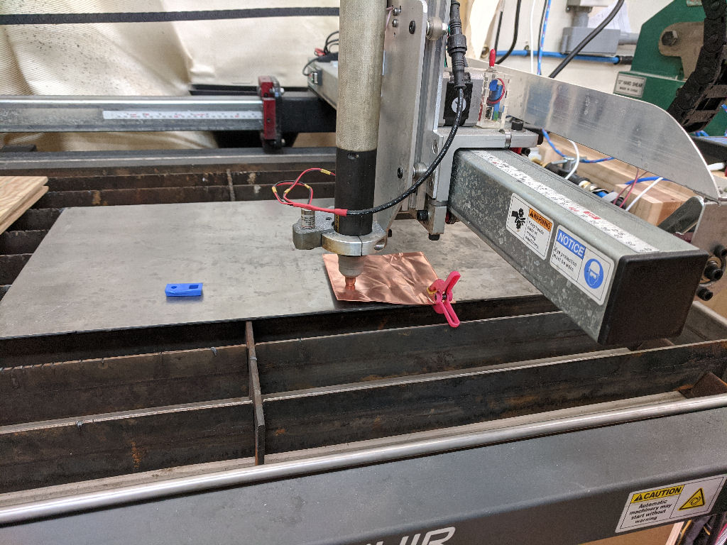
The torch obvious pressed the purposefully warped sheet into the plate, ‘calibrated’ and then, lifting up to what it thought was 0.250", the torch is still resting on the sheet that still wants to flex upward. Next test, try the ‘Ohmic’ probe. And here is the result:
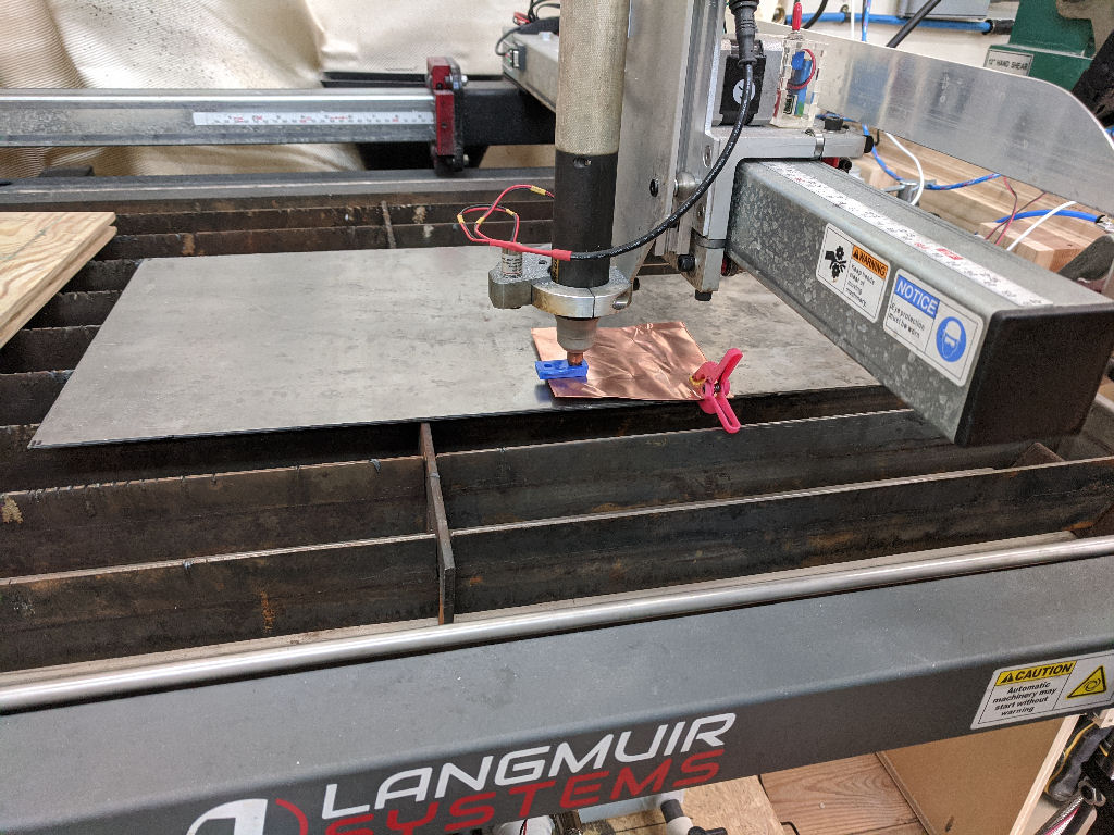
The blue object is a nylon shim, 1/4" thick, slipped into the gap between the torch and the copper sheet.
I’d call this an success ‘indicator’. The REAL test is cutting some thin material… gotta order some.
PS: I purposefully used the term ‘Ohmic’ with quotes as the original Ohmic Sensor was invented by Hypertherm (who else?) and may or may not be a tradename or mark. I don’t want step on those toes!