Plasma cutter connection

Hi all i hope that someone can help me to setup my plasma cutter to turn on and off, via my duet 3 control board? on my workbee cnc machine,
my plasma cutter is a Herocut HC6000 l/f pilot arc,and has to avation type sockets on the rear of the machine,one says arc voltage which is 2pin and the other says signal control which is 4 pin, what i would like to know is which socket is used and where to connect the wires to on the duet 3 control board, and would this need a relay between the cutter and the board.

Thanks for any help given

Mike.

First, welcome to the forum.

To clarify, you’re modifying a Workbee CNC router to support a plasma cutter?
If so, how to you have the work bed set up?
How are the aluminum cross pieces protected?
What control software are you using on the Duet?
What software are you using to control the Duet?

1 Like

I believe @Appletreedude has that Plasma Cutter so maybe he can tell you which pins on the 4 pin connector to use. It would be two pins and, yes, you need a relay driven from your duet board, connect to the COM and NO pins on the relay, polarity doesn’t matter.

If your system is currently using a PWM controlled Spindle, you can use the PWM output to drive the relay of the same voltage. Then, in your CAM settings, set your spindle speed to max. This will give you an on/off signal for the relay.

Hi Tom thanks for your reply.
what i have achieved so far is to establish what pins fire the plasma, iused a 5v power supply and touched pins 1 &2 with the leads this fired the tourched when removed fire stopped.
There is not a great deal on connecting a plasma to the duet board or a spindle , so i was looking at using one of the fan ports to turn the plasma on and off ,using m106 and m107 commands followed by g4 to dwell for x seconds.
i hope iam on the right track but would appreciate very much any help you can give.
Thanks Mike

I’m not sure how a 5V power supply factors into the torch fire. You just need a contact closure, either NO-COM from a relay.

Ok, that’s what you hook up to your relay contacts.

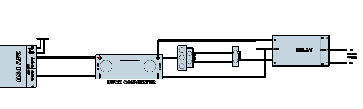
Yeah, good solution. The fan port should be fine, you just need to know what voltage is driven from that port. It’s typically 12V so you would need a 12V relay.

It’s easy to modify the SheetCam postprocessor to change the command and add the dwell for pierce delay.

Here’s a snippet from the Mach3 Plasma postprocessor.


function OnPenDown()
   if (preheat > 0.001) then
      post.ModalText (" G00")
      post.ModalNumber (" Z", cutHeight * scale, "0.0000")
      post.Text ("\n G04 P")
      post.Number (preheat,"0.###")
      post.Eol()
   end
   post.ModalText (" G00")
   post.ModalNumber (" Z", pierceHeight * scale, "0.0000")
   post.Text ("\n M03\n")                     <=== CHANGE this to M106
   if (pierceDelay > 0.001) then
      post.Text (" G04 P")
      post.Number (pierceDelay,"0.###")
      post.Eol()
   end
end


function OnPenUp()
   post.Text (" M05\n")        <==== CHANGE THIS TO M107
   if (endDelay > 0) then
      post.Text (" G04 P")
      post.Number (endDelay,"0.###")
      post.Eol()
   end
end


There are some GRBL post processors, probably what your Duet board uses.

Custom Post processors should go in:
C:\Users\USERNAME\AppData\Roaming\SheetCam TNG\posts
Edit an existing post, rename it, and save it in this folder…

Also, re your WorkBee center support bars, IFF you are using this for ONLY Plasma, you can remove the bars without any problem. They are there if you’re doing CNC Routing and are needed to handle the front/back torque from the cutting. There is no such torque with Plasma cutting.

IF you are also using this as a CNC router, then you may need to create an Exoskeleton OUTSIDE the cutting area to provide the support needed for CNC routing. I suspect a couple of 2040 bars, laying on their side, attached to the front and back will make it stiff enough.

Sure I can help, no problem, but I may move this thread to an ‘off topic’ category…

1 Like

Hi Tom once again thanks for your help this now gives me something to plod on with, and no doubt i will have more questions for you, there is a chap on youtube that uses cut 2D for his own plasma , the software which is provided by vetric aspire, which i have the pro version off
and he just alters a post processor to suite himself.

i do presume that the fan output would just work as when i connected the 5v psu without the relay connected, isn’t the relay just acting like a switch just as the fan would act like a switch using the m commands to turn on 5v and off 5v, i do have a 12v relay with a protective curcuit in one module i can use, but the fan output has only two pins ,the relay has three S, com and + terminals on the in side.

Anyway Tom, were are you in the world, i am in sunny Southport in the uk about 20 mile north of Liverpool in the north west of the uk.

Cheers for now MIke

According to the Duet documentation I saw, the Fan Output is selectable to be either 12V or Vin (typically 24V, but maybe your Vin is 5V). In either case, when you issue an M106 command, the two pins will have SOME voltage across them, and 0V on startup or after an M107 command. You CAN NOT connect these pins to your plasma cutter. You need the two fan pins to drive a coil of a relay. The relay contacts are then connected to the Plasma Cutter torch fire pins. The VOLTAGE of the relay coil has to match the fan output voltage.

Is Southport really ‘sunny’? :sunglasses:

I’m in the US, central North Carolina where SOME of the time it’s sunny :sun_behind_rain_cloud:

duet wiring FOR PLASMA CUTTER.pdf (393.8 KB)

Hi Tom, just wondered if you could look over this wiring diagram for me and let me know what you think, the connector marked fan after the buck converter is the fan input and output on the duet fans 1,2,3 are pwm

Ok, I’ll look it over and let you know by your Monday.

Whatever font you used to make the PDF did not translate well. This is how it came out on my screen, pretty much unreadable.

Thanks Tom. :+1:

What kind of Relay are you thinking of using. A link would be helpful.

HI TOM IT’S JUST A BLUE COLOR TYPE RELAY WITH 3 PINS ON THE INPUT SIDE

    • AND S ON THE OUTPUT SIDE N/C COM N/O IT IS ON ITS OWN LITTLE BOARD
      TO PROTECT THE MAIN BOARD FROM BACK SURGE, GOT IT AGES AGO TO USE ON A arduino BUT NEVER USED IT IT’S A 12V RELAY

THANKS MIKE
THANKS

HI TOM SORRY ABOUT THAT, HOPE THIS IS MORE READABLE , LOOKFOWARD TO HEARING FROM YOU.

CHEERS MIKE
DUET - PLASMA WIRING.pdf (91.4 KB)

Ok, I can read it now and it is not correct.

EDIT: Here is how you can fix what you sent to me:

  1. Disconnect Relay COM from the Buck Regulator.
  2. Disconnect Plasma Input Connector Pin 1 from Buck Regulator.
  3. Connect Plasma Input Connector Pin 1 to COM pin on Relay.

Done.

1 Like