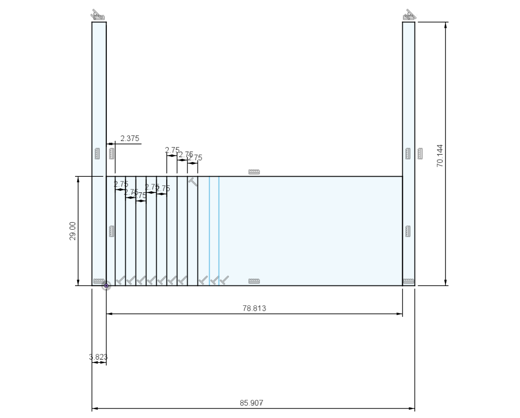
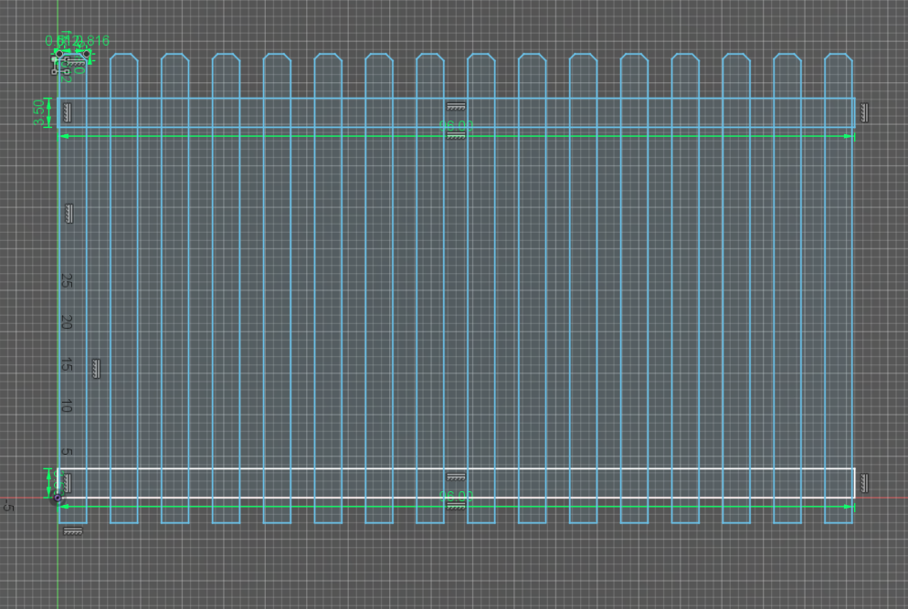
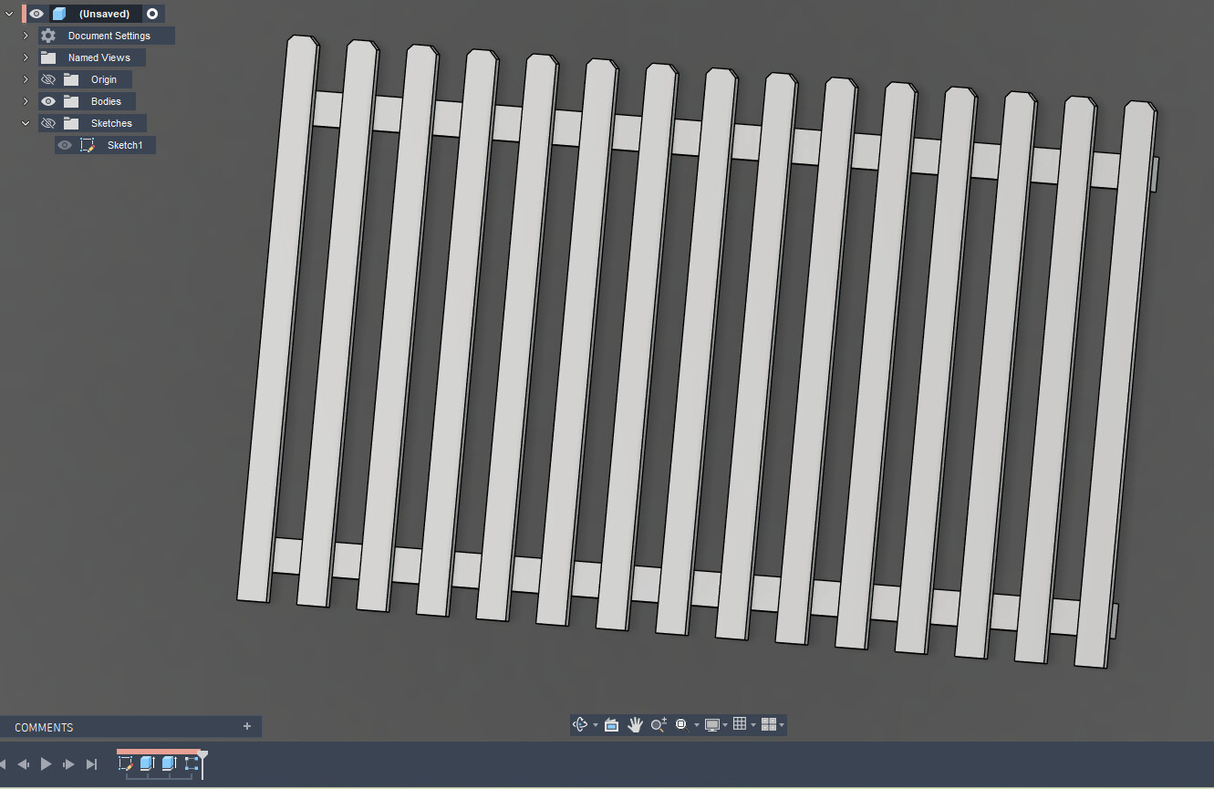
Does anyone have a quick way to lay out pickets in fusion 360? I like to create 3d models of my jobs for shop drawings. I have not found an efficient way to set pickets spacing quickly. Currently I am manually dimensioning each picket which is very slow. Sometimes I will set a center point and mirror them but its not always super quick. I also sometimes pattern on path after its all extruded but that seems wonky sometimes too. Any help is greaty appreciated!
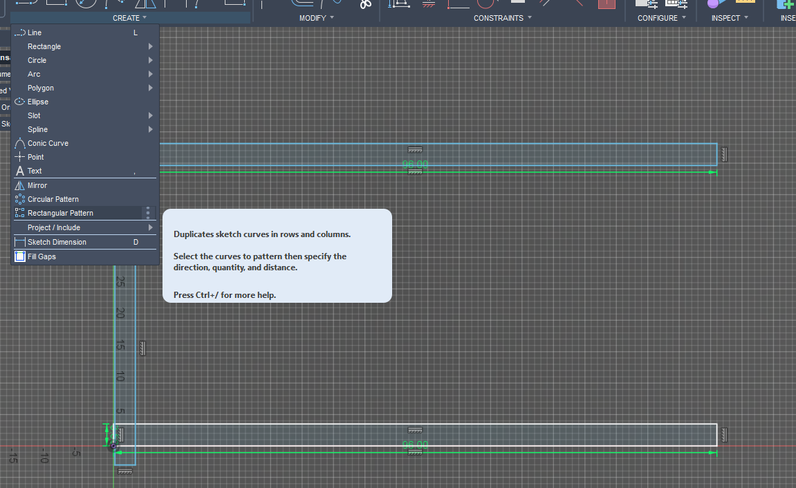
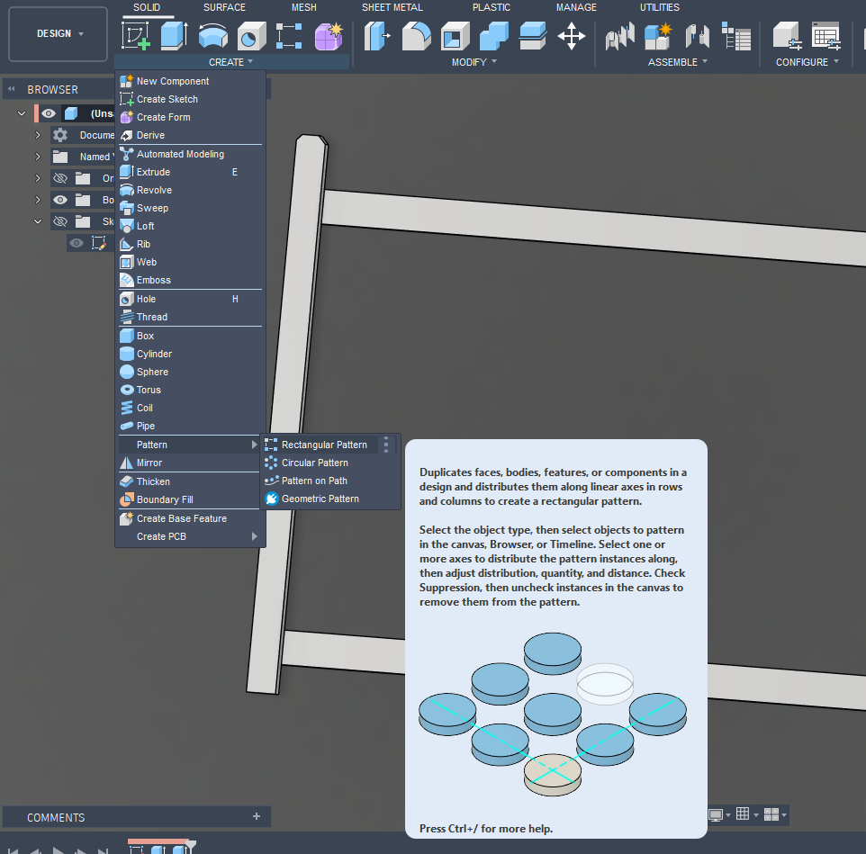
Use “Rectangular Pattern”
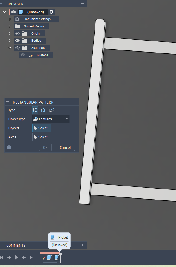
Pick “Rectangular Pattern”. Double click or hold down shift while selecting multiple items:
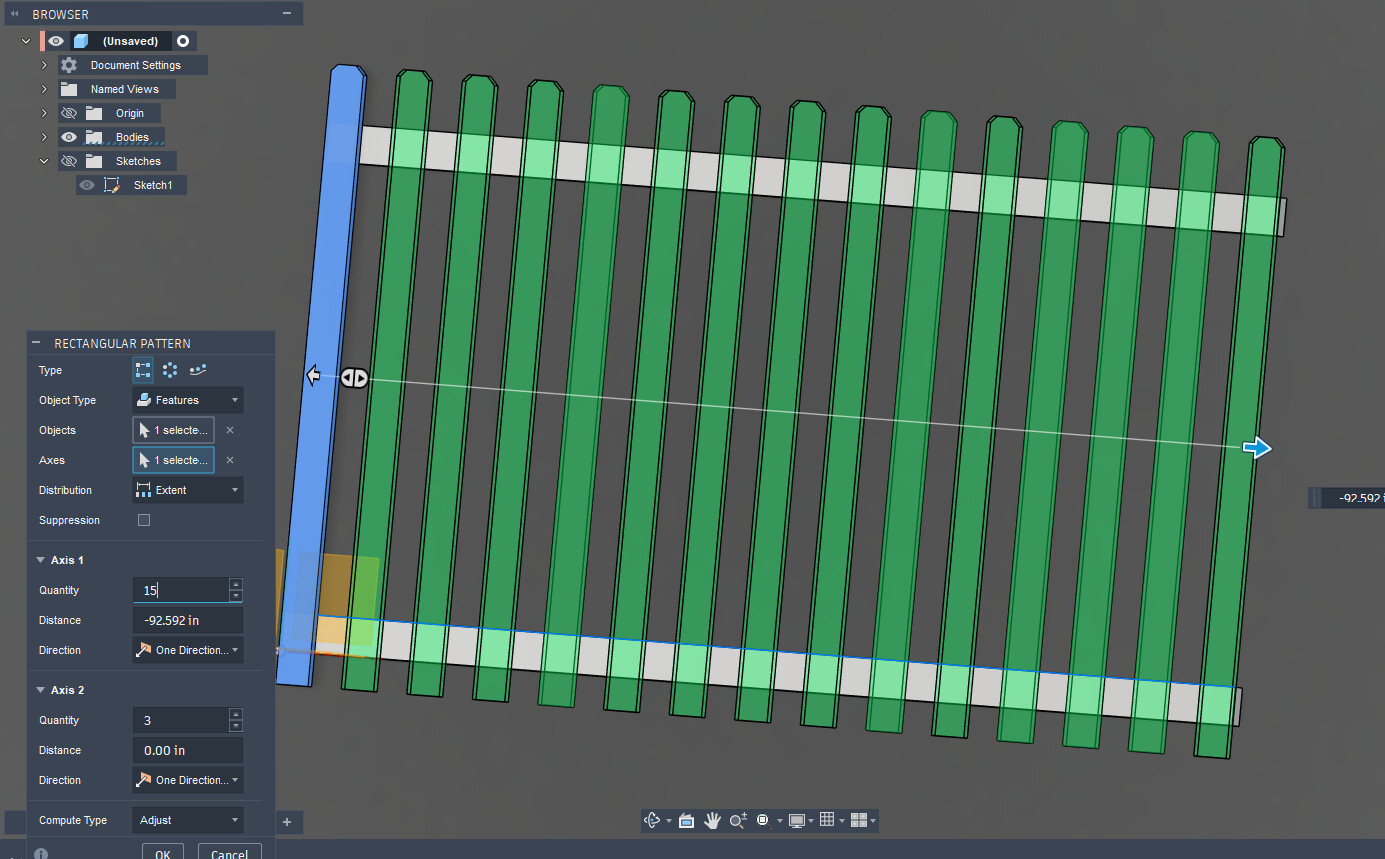
Now stretch out the pattern or determine the spacing, increase the number of instances:
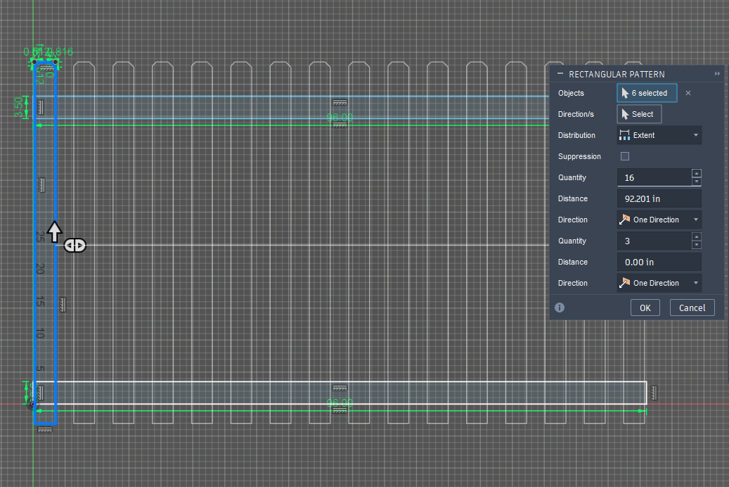
Hit [Enter]
But an even better way is to extrude your first pieces, then copy with the rectangular pattern a feature from the timeline or a body:
1 Like
That was extremely helpful. thank you!
1 Like
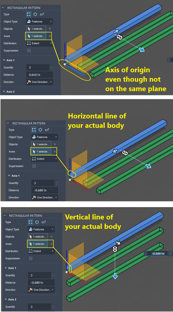
Keep in mind that in both examples I used, they will ask for your axes. This is where Fusion is very tolerant. It will allow you to pick any straight line in you sketch or on the body or any of the axes lines of the origin even when your sketch or body does not lie in the one of the planes of the origin. Fusion will even allow you to pick construction lines.
2 Likes
Ok that is great. I have trouble because I will find features and then they dont seem to behave the same way the next time I try. Part of it is fusion being glitchy and part of it is my drawings being a portal to hell. I am way over my skis with the things I am designing. I get hung up on a lot of my drawings. My business is doing well and my customers love the drawings and they really make fabrication a dream, but I need to hire a tutor. I am designing some things that are quite difficult for me to pull off in fusion. The help is greatly appreciated. I think a few tweaks in my process would grealy benefit my fusion skills. things like: not being able to connect lines from different sketches really puzzles me and i end up doing everything in one sketch. sorry for the long response. I am making changes to this drawing at the moment and its making my brain hot…lol
1 Like
I know what you mean. I am still learning as well. I believe we are both violating the cardinal rule of keeping the sketches “fully constrained.” Tin gave a tip a few days ago to limit your use of “Trim” because if often removes constraints.
I use “Trim” a lot so I need to stop that. When I have a sketch that misbehaves I will often move/copy the part. If you try moving some of those poorly constrained sketches, it is pure evil.
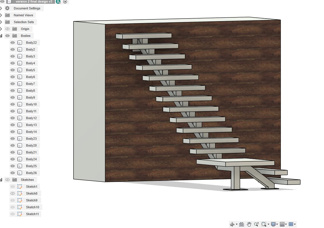
Very cool rendering with the stairs!
1 Like
I just so happened to have a customer stop in last night to pay me and he told me the constraints were screwing my drawings up. He a wizard with Solidworks and mentioned the coincidece is why i cant snap lines from drawing to drawing. Its all just the hiccups in being self taught. I use trim all the time. That is really good to know. It seems like the program is full of gremlins but its just my lack of knowledge. Thank you I think they are looking pretty cool. now time to add handrail and bid the damn thing lol. Its for my shop landlord and he likes nice stuff! Lucky to have great customers like that.
2 Likes
This function is call “projection” in Fusion.
One of the main differences between Fusion and SolidWorks is the work flow. Fusion uses the Top down approach where SolidWorks takes the bottom up approach. This makes a big difference of how one would tackle an assembly.
Story of my life lately, some weird and wonderful projects coming my way.
2 Likes
That is a great video but I will need to watch it a few more times. When he applied joints to other components, I didn’t really see how he did it…unless it was “repeat joint” in the right click menu.
Lots of things to absorb and think about.
I do like the Top Down approach as I can see the exact angle and orientation of my part. But later, when setting up a file for printing, you have to re-orient all those parts on the same plane.
Learning stuff every time I do something in Fusion 360. I would imagine that is true with any of the large programs like Solidworks.
2 Likes