Hello,
I am new to this type of work and am having trouble with Fusion 360. I purchased a DXF file of the American flag with the Don’t Tread on Me Logo on it as well. When creating a tool path it crossed over several of the intended cuts. I contacted Fusion on their forum and was advised to select a parent sketch and reduce the lead in and piercing values. I reduced the values and am having the same issue. The Langmuir tutorial videos did not cover selecting a parent sketch. Any help would b greatly appreciated.
Are you talking about when you cut it or just the cut path on fusion?
If you’re just talking about the cut path on fusion it shows it all… the cuts the lead ins and the rapids between cuts.
The green lines are the lead ins, the yellow are the rapids and the blue are the cut lines.
When creating the tool path in fusion.
I am familiar with the green lines being the lead in and the blue being the cut lines.
I am having trouble with the program generating the tool path even after reducing the lead in values in the linking tab.
I’m not sure what you mean by saying it crossed over intended cut lines?
It wont generate a cut path if there is interference with other lines.
Can you get a screenshot of the cut path it generated and post it?
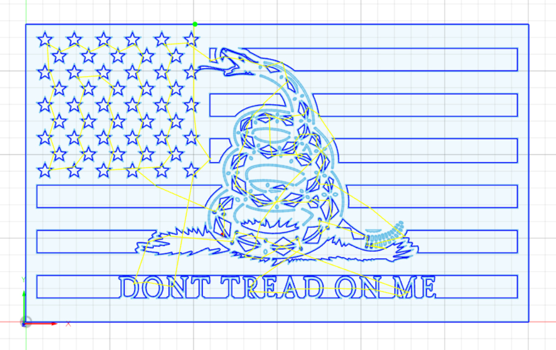
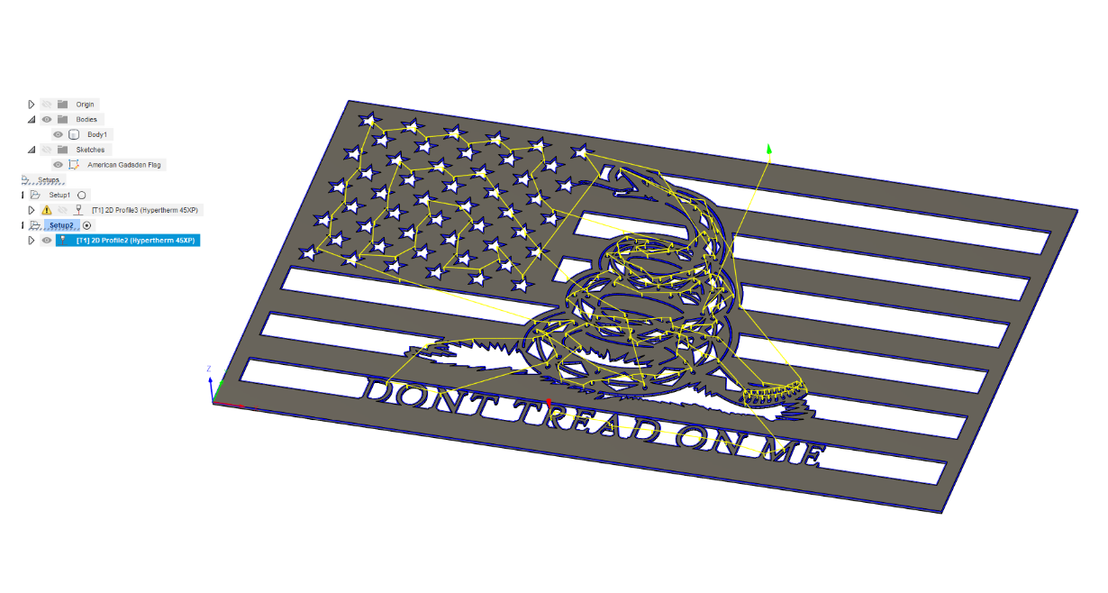
All of the geometry cuts have been previously selected, The outer perimeter lines of the snake, the small ovals and the rattle ovals did not generate to the tool path. I have since reduced the lead in values and I keep getting the same error. When I sent this to Fusion it appears they were able to generate a tool path. Maybe I’m missing something. The second image is what Fusion sent me.
Thanks
Just curious where you may be at with those settings at this point…?? A good starting point for lead in is twice the size of your kerf… Turn lead-outs off as well…
See if that makes a difference for you…
I have reduced the values to twice the kerf and even lower with the same results. I’m stumped, maybe there is another setting somewhere that is off.
You’re going to have to reduce your pierce clearance to get those small parts to cut plus probably a zero lead in.
2 Likes
Fortifyfabworks,
Thanks. Ill try that and get back with results.
I would break this into a few toolpaths (profiles) in 1 setup. One for the stars, one for the lettering, one for the flag bars & outside cut and one for the snake. It may be having trouble generating the paths due to the complexity of jamming all that into 1 toolpath. Breaking it into multiples allows it to do less work in each profile. They’ll all end up in the same tap file so you don’t need to worry about having to load multiple taps to cut.
The small ovals may need either a 0 lead-in/out (I almost never use a lead-out on small pieces) or a no-offset cut so it cuts on the line instead of trying to squeeze the kerf inside the hole (I bet the kerf is too large to make it an inside cut).
1 Like
So if you split it into multiple tool paths does it then link them back together somewhere so you can send all the g code to fire control at once or do you just run one and then the next etc ensuring the same x/y zero and metal doesn’t move? New to this trying to learn.
Thanks John
When you put together different profiles with different lead ins or different whatever just make sure you start with your inside cuts first because the way it will generate the gcode it will do each profile in order so if you accidently put a outside cut in profile 2 but in profile 3 you have a inside cut it will go back and do that inside cut after the outside has already been cut.
When making the gcode make sure you have the setup highlighted in the dropdown menu on the left and it will generate code for all the profiles.
1 Like
So if I understand correctly, you are saying I can run a profile for the really small intricate cuts. Then build a second profile under the same setup and cut the more straight forward stuff at a faster rate or different leadin lead out setups. When I run the post process it will pull both profiles in the order they appear in the browser and the CNC will adjust mid stream as it hits different profiles?
I will give it a try. Thanks for the recommendation
Thanks you so much for your help. I did all that and got it sent to g code. I will try the cut this week.
Chris
1 Like
As long as the profiles (toolpath definitions) are in the same Setup they’ll all go into the same tap file. You only need to load and run the single resulting tap file. If the profiles are in different setups, they’ll go to separate tap files.
I rename the profiles (they default to Profile 1, Profile 2, Profile 3…) to what they are - like outer cut, small holes, no offset lines, etc. The name is included in the GCode as a comment and you can easily find the starts of any cut groups if you hit a problem. Not as critical with FireControls restart functionality but still nice for clarity.
1 Like