im trying to cutout an anchor with a hole at the top, but when i set it up the simulate and firecontrol only show the outside, any advice on what im not setting up right?
also the files on fireshare dont showup on firecontrol and im not able to open anything up to check the setup
You have to unzip your files first from fireshare.
In fusion 360 if your kerf width, lead in radius, lead in, lead out and Pierce clearance add up to more than what Fusion 360 can fit in the space you’re trying to cut it will leave it out.
1 Like
how would i check the clearace space?
how do i unzip the files?
I’m not really sure what operating your system you’re using but in Windows it would normally ask you if you want to unzip a file when you double click on it in the file navigation folders.
Or you might have to download a unzipping app.
And as far as knowing whether it fits or not well you know for sure it doesn’t currently so look over those parameters that you would have had to fill out in the 2D contour menu and the manufacturing workspace in fusion 360 and see if maybe you have an extra zero or a decimal place in the wrong place or potentially your geometries just too small.
And then there’s the off chance if the geometry happens to be a acutely intersected semicircle, Fusion 360 may not recognize it but this doesn’t happen as often is just being too big to fit into the geometry.
2 Likes
Export and post your f3d file and I can take a look
1 Like
anchor v4 v4.f3d (124.9 KB)
pug v5.f3d (207.4 KB)
theres a couple
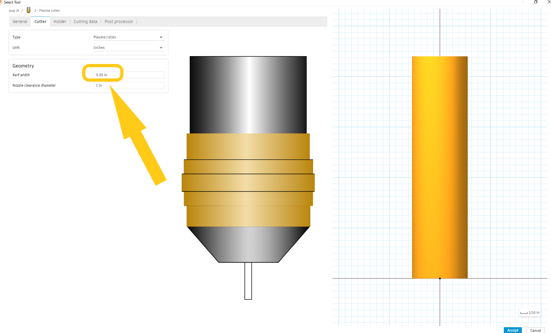
The Kerf width of the tooling you are using is much too big. instead of .55 try .055
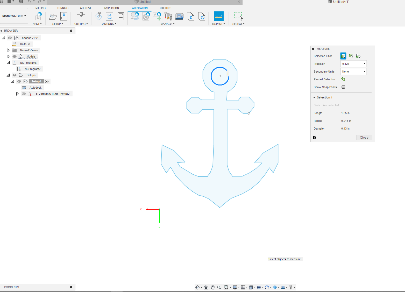
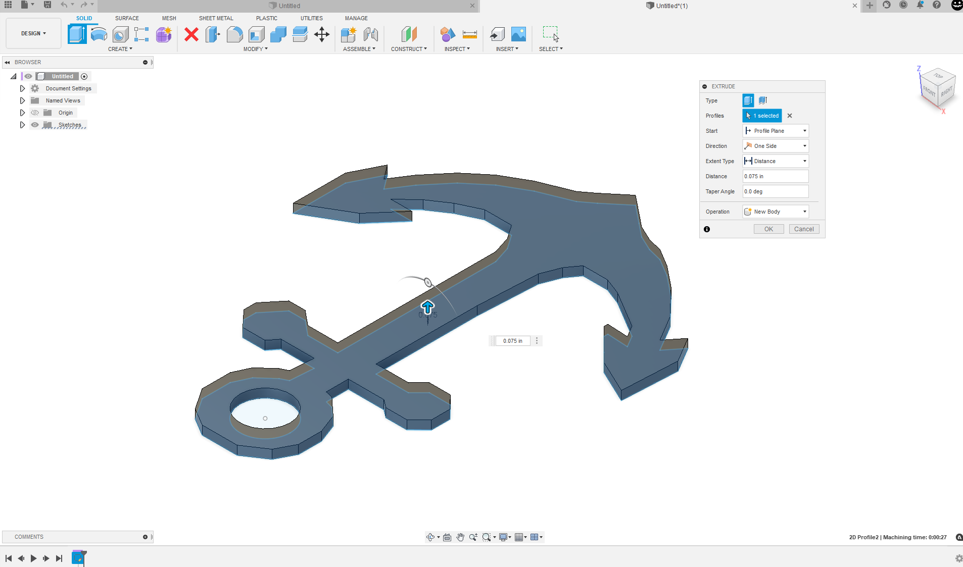
both of these are very small. the pug’s square is about 5" and the anchor is 2.75" across and its mounting hole is .21" (which is also my preferred size for deck screws )
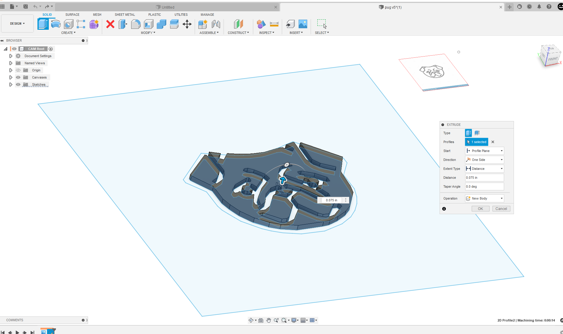
For both these designs going back to the design work
Space and extruding these profiles into bodies is the first step.
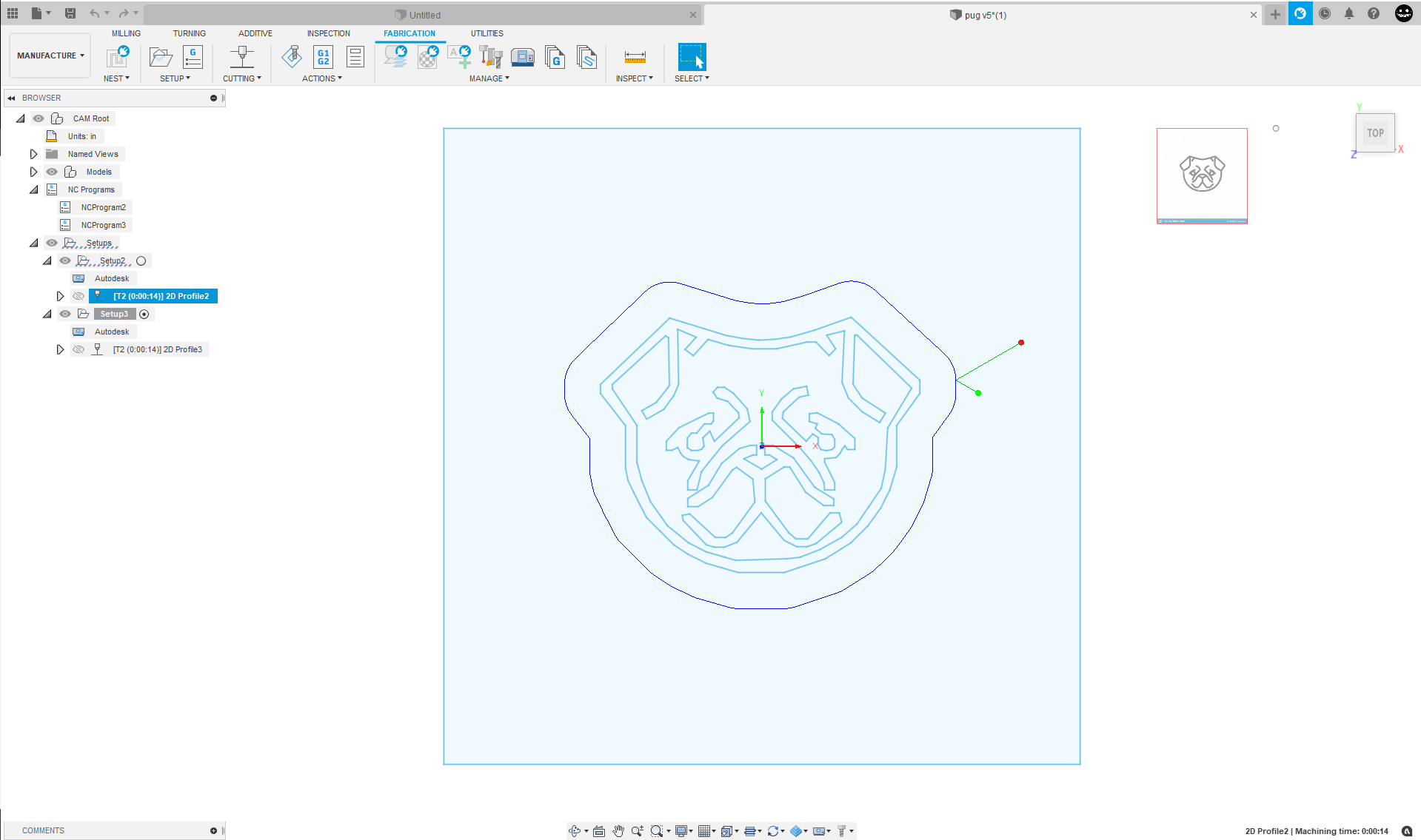
I also scaled up the pug to 1.25. it was too small to be practical to cut
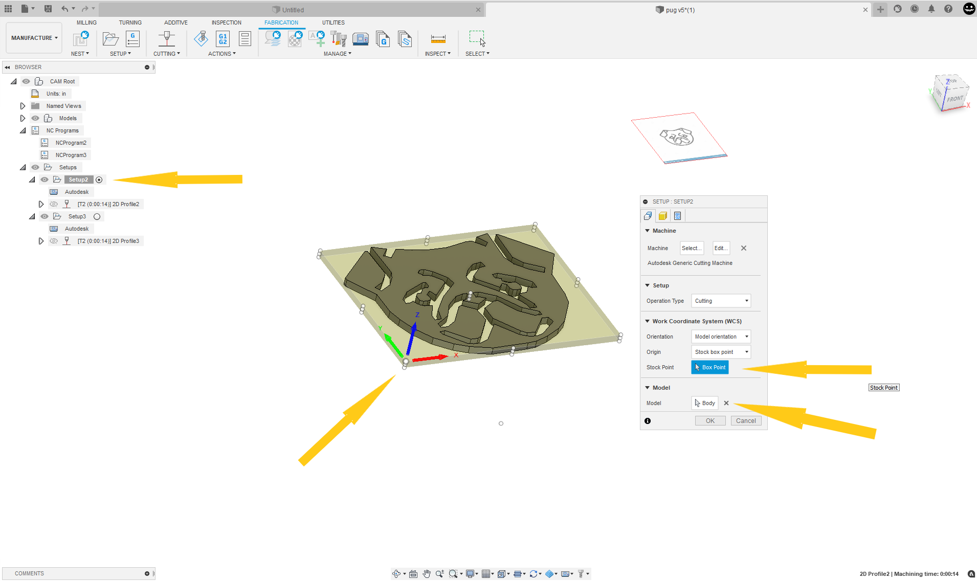
now back to the manufacturing space and let make some changes to your set up
change the stock box point ( ends up being origin in firecontrol) to the bottom left of the model
Change model to body
do this for the anchor too
now with a reduced lead in and kerf width fusion generates a tool path
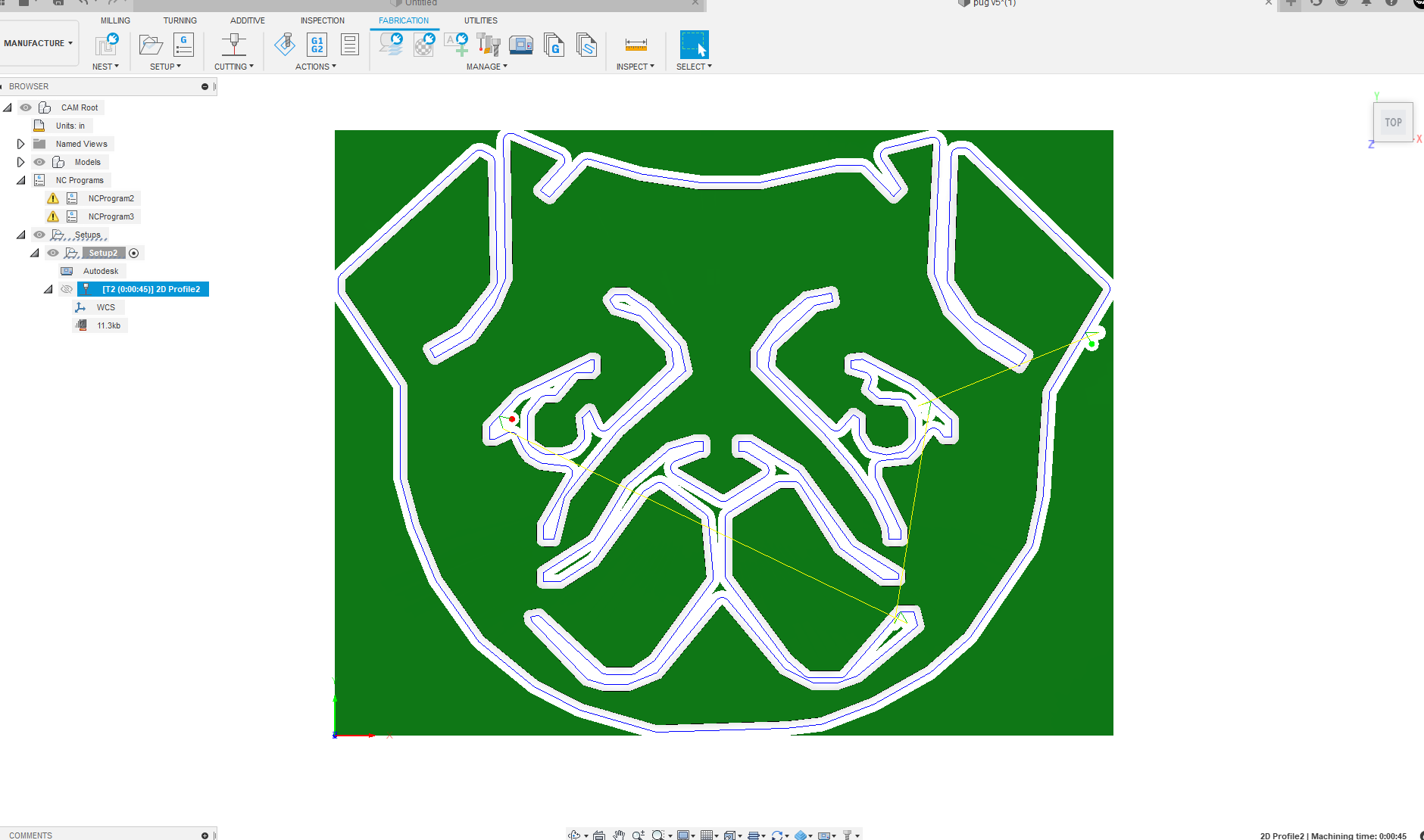
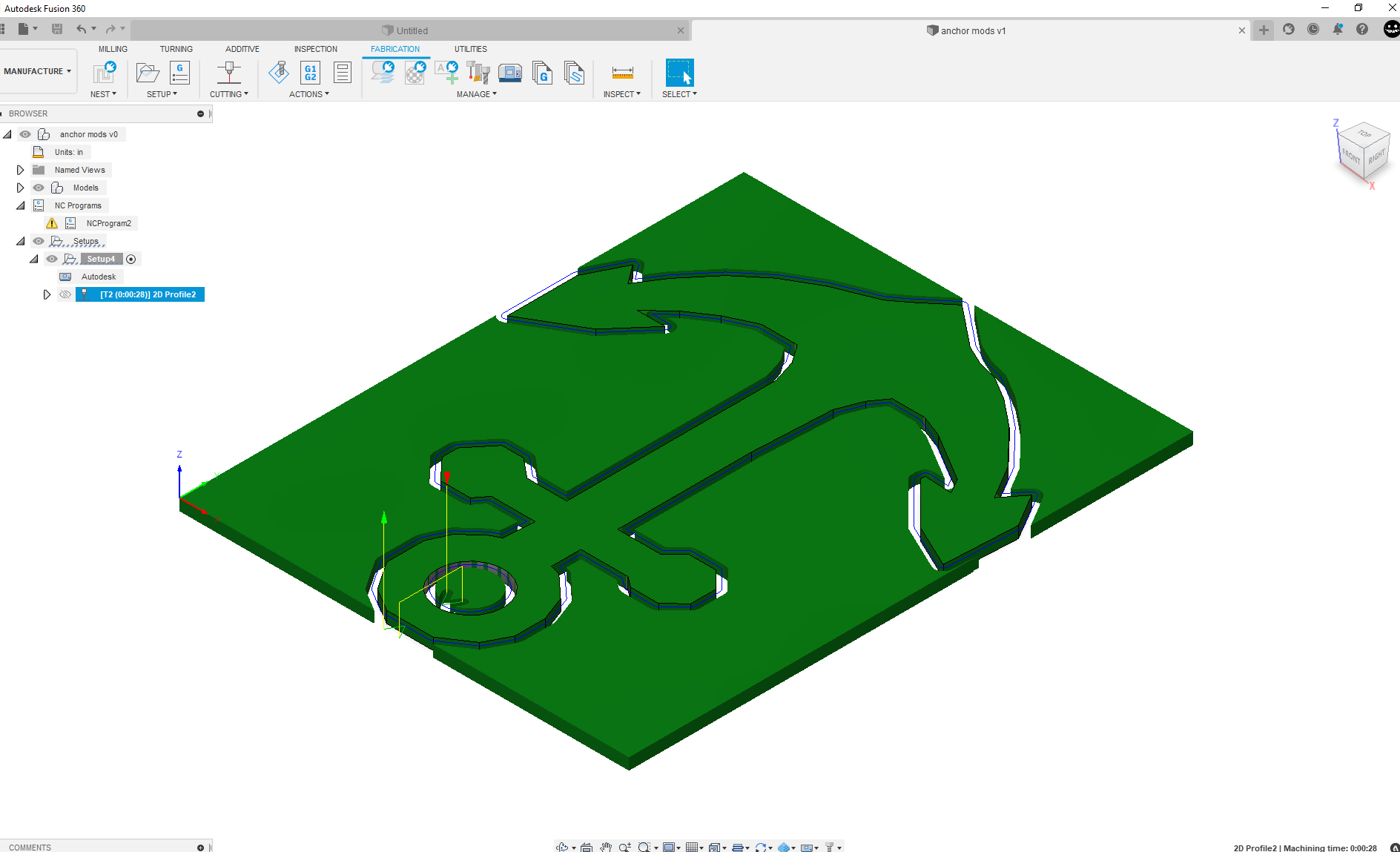
these toolpaths could be fine tune further if desired.
Attached are the 2 modded F3D files
anchor mods v1.f3d (162.8 KB)
pug v5 mod v0.f3d (333.1 KB)
see how this work for you.
If you click my avatar there is a link to a series of basic fusion tutorial videos I have started to put together please check them out.
2 Likes
This is how it done in Windows 10
How to unzip files in Windows 10 (this is a copy and paste from Google)
"Right-click the ZIP file.
In the drop-down menu, click “Extract All…” The zip wizard will appear. …
If you want to unzip the files to a different folder, click “Browse…” and choose a location.
Click “Extract” and the files will be unzipped and copied to the folder you chose."
1 Like
Figured out the unzip. I knew the drawings were small but wasn’t thinking it’d be a problem in showing up, forgot to upscale them
Thanks for all your help with my constant questions
1 Like
What’s the benefit of extruding vs doing like langmuir says and doing without?
It allows Fusion 360 to know what is the inside or outside of an object while developing toolpaths.
If you have not extruded your profile into a body Fusion 360 may or may not know what side of the line to cut on in the interior geometry.
Definitely you can do it with a sketch without extruding but you can also make an error on line selection manually selecting it that way.
Basically the benefit is not running into the one of the problems from earlier in the topic.
I would try it for yourself and the benefits will become very clear.
1 Like
rimmy v6.dxf (1.1 MB)
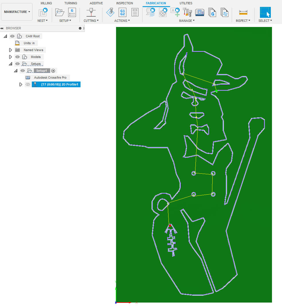
bear with me please. i got pug fixed without extrusion, but instead of just the buttons missing i cant get anything but the attached. watching your vids now to see if i can catch my problem
Attached is a FD3 of the rimmy files so all the menu should be populated with my parameters
Rimmy Finishing touch Langmuir forum v1.f3d (312.3 KB)
It managed to developed a toolpath with no lead in lead out for all the geometry.
I set the kerf to .036" which maybe be the problem you are having at .05" (or whatever it is set for )
rimmy finishingtouch langmuir forum .nc (13.1 KB)
here is a cut file at 200ipm for the pro .06cut height .015pierce height
I do not have any super detailed videos on the cam environment(manufacturing workspace) yet but maybe in the future.
i looked through the hypotherm 45 xp settings and put the recommended in for my settings. how will i know the size kerf i need in the future if i run into similar? should i make the holes bigger?
from the vids the only difference in setup was i didnt mess with lead in radius.
the kerf width is listed in the 45xp cut charts (far right column) these will be close to actual kerf width and yes make the holes bigger if possible or reduced to a single line cut for fine detail.
setting a smaller kerf width then the actual kerf width will end up cutting a larger hole anyhow.
1 Like
even using your parameters and trying to put entry and contour points where yours were roughly im still not getting it to make a toolpath like yours did.
not going to keep yours cause i need to figure out how to do this for myself, would a lead in radius affect me?
if it was too big it would not develop a toolpath
just figured it out, the lead in lead out being selected was the problem, why i have no clue but its generated with no problems so thanks.