I’m betting there is a pretty obvious and simple solution to this but I figured I’d ask before going through consumables to figure it out…
So, how do I set a “line” in CAM to be cut in a single pass so that it can be easily bent (and welded after)?
I’m betting there is a pretty obvious and simple solution to this but I figured I’d ask before going through consumables to figure it out…
So, how do I set a “line” in CAM to be cut in a single pass so that it can be easily bent (and welded after)?
So, while you’re in CAM choosing loops and lines… I create another separate 2D profile in which I select “Centered” for the sideways compensation. This will give you a kerf right on top of a line… See pics below…
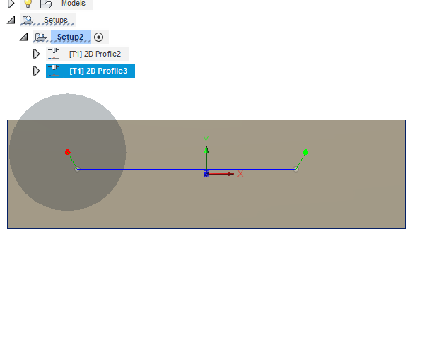
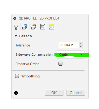
And, of course don’t forget to eliminate lead-in’s and outs on your line… I missed that when capturing the screenshot…
Give it a try and let us know how it comes out…
Ok that all makes sense, thank you. I’m just unclear now on putting these actual “seam lines” in the CAD drawing. If I just place a single path where I want them, when I extrude the shape and go to CAM, these paths are not visible. Should I not extrude in cases where I want these lines?
EDIT
Ok scratch that last bit of confusion, must have been a Fusion360 bug. I went through again and tried and this time the paths did show and I was able to follow your instructions. Thanks!
In addition to what @KX9M said also make sure to set pierce clearance to 0.
I always do this type of thing in two tool paths…the lines first then i run it back to zero and load the next tap file and start from there.May be a easier way but that how ive done it.
@Heath you can do it your way or you can highlight Setup and post process. This will post both tool paths at the same time in one tap file. No need to load multiple tap files or return to zero. Just make sure your tool paths are in the order you want them to cut on the machine.
Also you can highlight Setup and simulate the entire operation.
It sound silly but make sure to cut all the inside features first. I run bend lines, inside profiles, bolt holes, outside. Keeps the sheet form moving too much with the heat or water hitting it.