I wanted to share my solution for the ever frustrating issue with flexing or bowed material during IHS. I installed an Ohmic Circuit of my own design on my Crossfire and just recently uploaded 14 short videos to my youtube channel for viewing. It’s working great and the flexing problem during IHS on thinner materials is a thing of the past! No need to try and clamp down thin material to address the flex that occurs during the downward travel of the torch during IHS. I’m including a link to my channel if anyone is interested in checking out the videos.
WHEN YOU CLICK ON THE LINK HOVER OVER THE “YouTube” TEXT AT THE BOTTOM OF THE SCREEN AND CLICK ON “WATCH THE VIDEOS ON YOUTUBE” TAB OR YOU’LL MISS VIDEO 11).
The link will direct you to the playlist where the videos are posted and they are labeled starting at Ohmic 1 and so on. Due to my unfamiliarity with setting up the channel (I just set it up over the last two days) one video uploaded as a short (#11) so in order to see all of the related videos one must view the playlist which has all the videos in order (1-14).
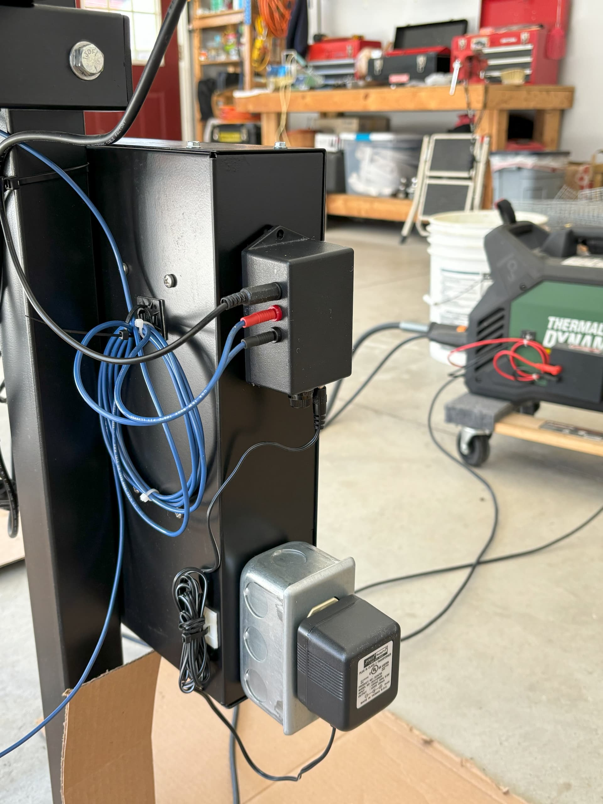
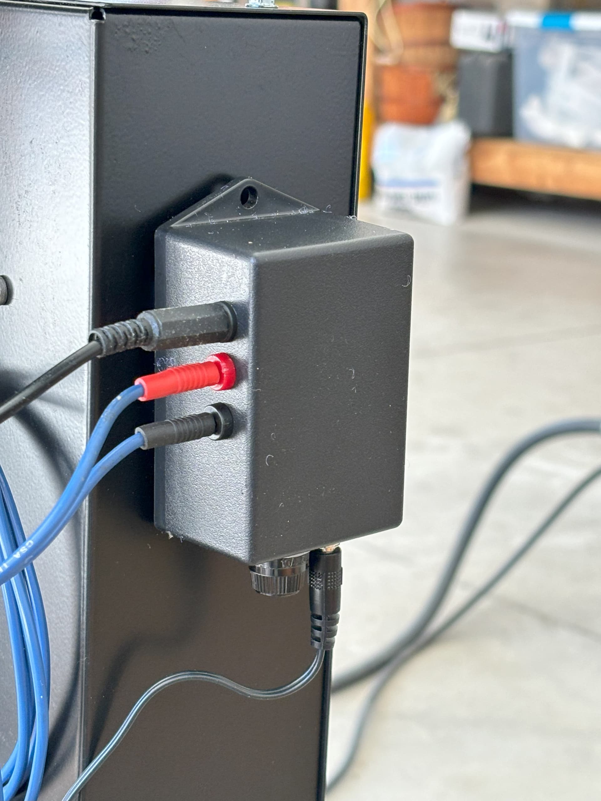
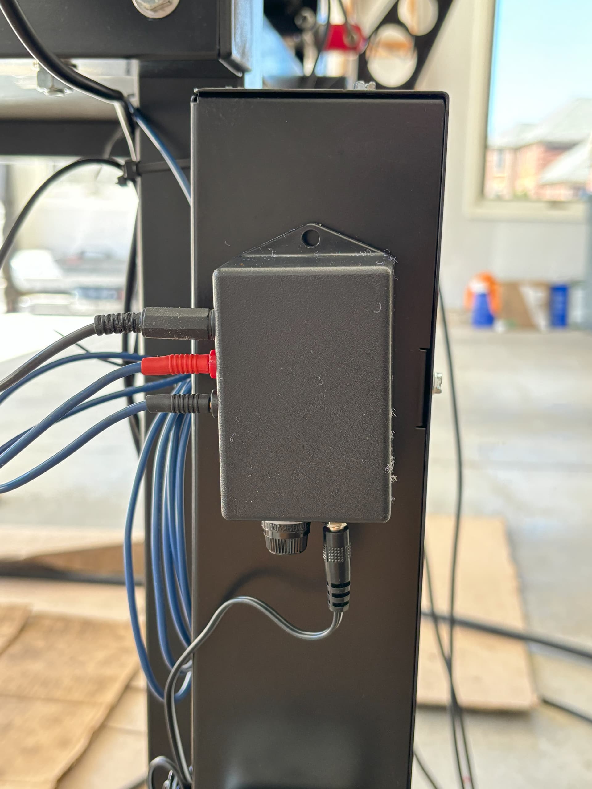
And here are a couple of pictures of my circuit.
Leave a comment if you’d like.
Interesting contact cap on your torch. It’s interesting that the plasma shape isn’t affected by the shield.
I didn’t watch all the videos, TL;DR, having mostly skipped to 10 and 12 to see what you were actually doing. In video 13 it seemed as if the sheet moved as the torch touched it, just as it would with the normal IHS. I’m not sure if that was an optical thing or it actually moved, but a far better test would be a thinner piece that was warped from cutting as a more realistic test and demonstration.
Hello,
You are correct that the material in video 13 flexed down a bit during IHS when the ohmic circuit was enabled. And there’s a reason for that occurring that I forgot to mention in the videos. I’ll have to add an additional video explaining the reason behind that as it does not interfere with the correct Z axis sync during IHS.
Videos 4 through 8 explain the difference between Z axis sync during IHS with and without the ohmic circuit enabled and why the ohmic circuit works. Operation is verified visually with the DMM and the Firecontrol screen.
But the reason the material will flex downward slightly during the Ohmic IHS loop is because Firecontrol continues to drive the torch assembly downward for a fraction of a second after the IHS relay contacts open. Firecontrol will not start the upwards motion of the torch until it senses that the IHS contacts have remained opened long enough so there is a short lag from the time the IHS contacts open and the point that the downwards motion of the torch stops. The flex in the material that you see in the video is the lag time. At that point the torch starts its upward motion and when contact is broken between the Ohmic cap on the torch and the material the Ohmic IHS contact closes and Firecontrol will then zync the Z axis as being at the top of material. So it doesn’t matter that there is some springback of the material because the IHS zync doesn’t occur until the contact with the material is broken and by that time the material is back where it needs to be for correct zyncing.
I’m including a quote from Aksel Langmuir on this topic from one of my communications with him if you care to read on. It was his response to the lag time that I was seeing.
“To answer your second question, the answer is a bit complicated. If you watch the brass IHS contacts closely while simply jogging the Z-axis up and down its full travel length several times, you may notice that the contacts will momentarily separate from one another, them almost immediately snap back together. Some variance in the bearings and variance in the preload of the bearings to the linear rails causes this to occur randomly every once in awhile. During the IHS loop, FireControl will monitor how long the brass contacts are separated, and if they stay separated for long enough (still only a fraction of a second), then it will stop driving the Z-axis downward. Once the downward movement has stopped, IHS moves the Z-axis back upward until the brass contact switches are back in contact- this is when the Z-axis is zeroed.”
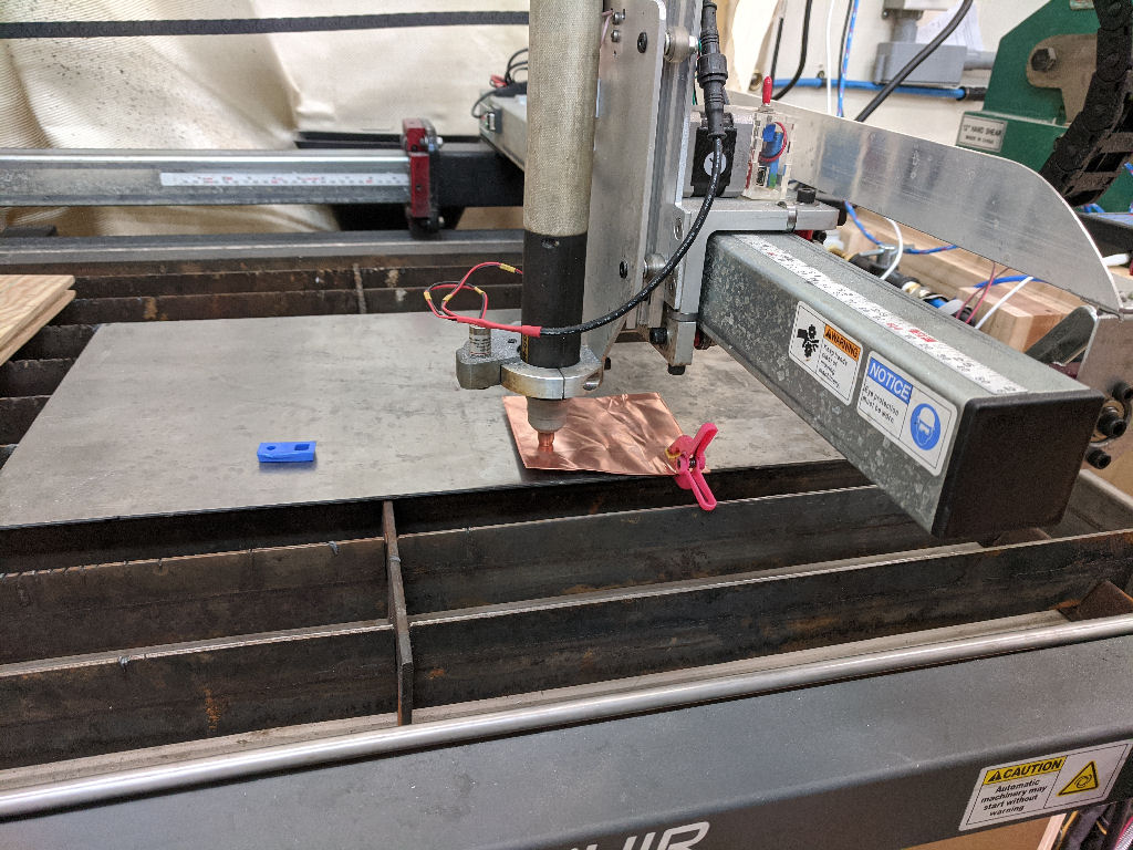
Well, in any case, if you want a real test of how good it is, you can try this: In this example I used a 15mil sheet of copper foil as the ‘workpiece’. Obviously I wouldn’t cut that with a plasma cutter, but it does provide a very effective measure of the quality of the ohmic sensor and, @langmuir-aksel 's point about over travel, should be the case no matter what material was in the ‘way’, it’s a constant that should be able to be cancelled regardless.
I’m sorry but the circuit design is proprietary as I’m going to Beta test it sometime later this year here in Southeast Michigan with a few local Crossfire end-users. If things work out I’ll be marketing it as an Add-on to the Langmuir series of plasma tables.
Hello,
I’ll save your contact information and contact you when I have some test units available. I hope to have something ready by late fall. Thanks for reaching out!
Hello all,
I just saw the latest posts on my ohmic circuit. Yes it’s been awhile since my last post. To bring things up to date - yes it does work and I’ve been using ever since I posted my videos. Unfortunately I’ve been extremely busy since that time and I’ve been chomping at the bit to get back to it. Yeah, I know, a year and a half! I never thought I’d be this busy in retirement!
If anyone living in Southeast Michigan is interested in seeing it in operation I would be open to setting up a day for an onsite demonstration. I live in Washington Township, Northern Macomb County.
So here is an update:
Since I posted my videos I took my design from the simple breadboard design using spare parts from my workshop and designed a circuit board layout and came up with a nice unit that I would eventually like to market. It’s actually ready to go except that I need to encapsulate the circuit board to ensure proprietary ownership. You know, so no one steals my design.
Through my testing I’ve concluded that it does not work well if you’re using a water table as the water that splashes up on to the metal causes problems. I’ve since stopped using the water table. I have however come of with a solution to that so that I can start using the water table again (more on that later).
The other thing that I was trying to do was to come up with a way to add ohmic circuit capabilities to any plasma torch but that has proven to be a difficult problem to overcome.
My plasma torch, as I described in my videos, does accept a shield cup that in turn accepts an OEM ohmic clip. With that ohmic clip in place I attach that feed into the ohmic circuit and the circuit works as designed. So if you have a machine torch (not a hand torch) on your table that will accept an ohmic clip then my circuit will work with your setup. If not then you can’t use it with just a regular hand torch. That being said, I think I’ve finally come up with a solution that, using the same circuit with a slight modification, the circuit will work with any torch! Hand torch or mechanical torch. I just need time to modify my table with the new design as I’ve actually been researching the part that I need to make it work.
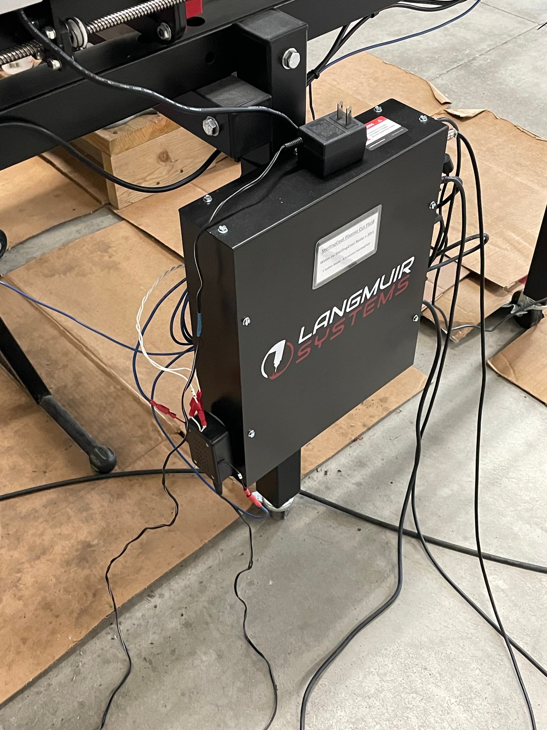
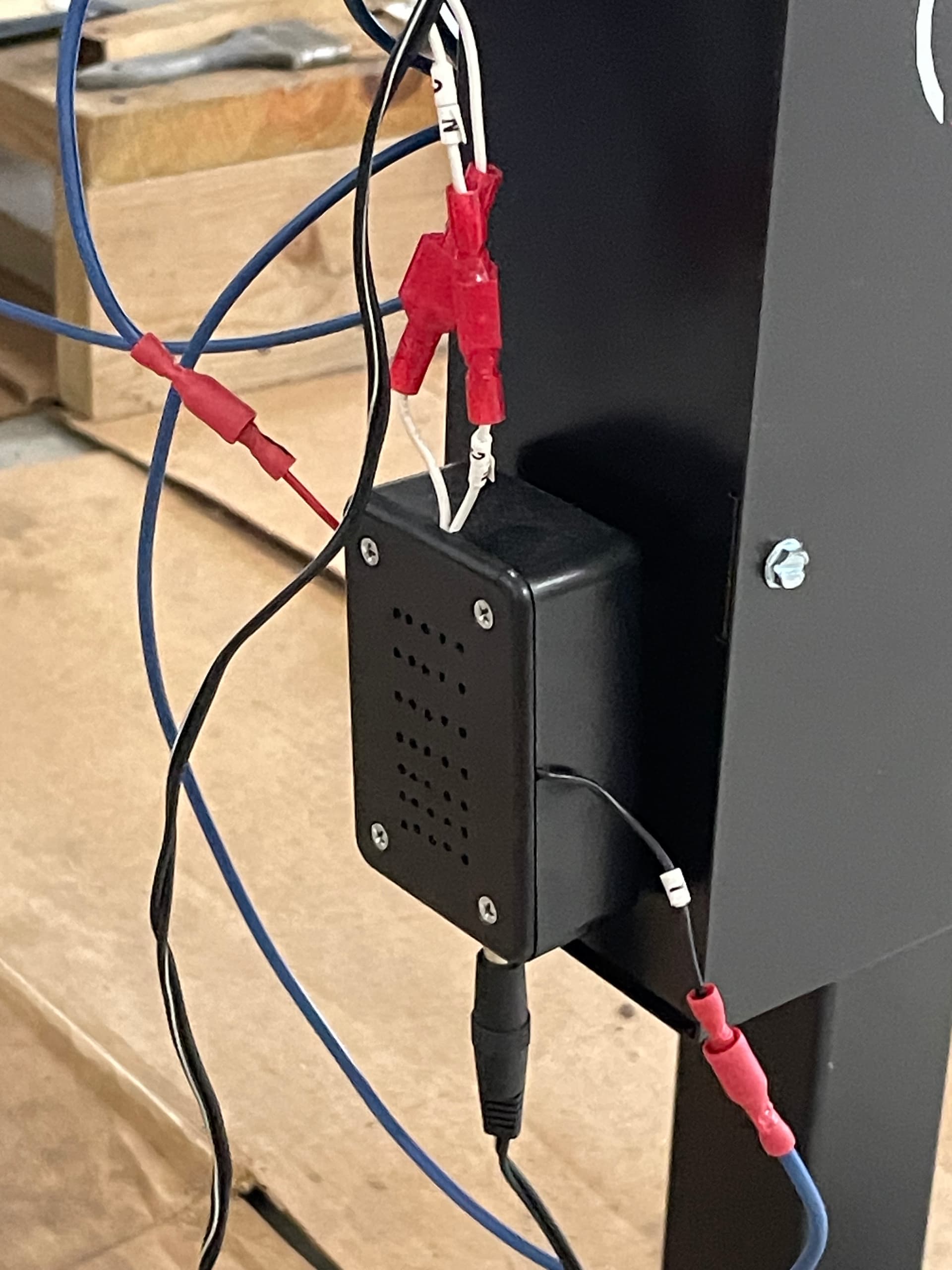
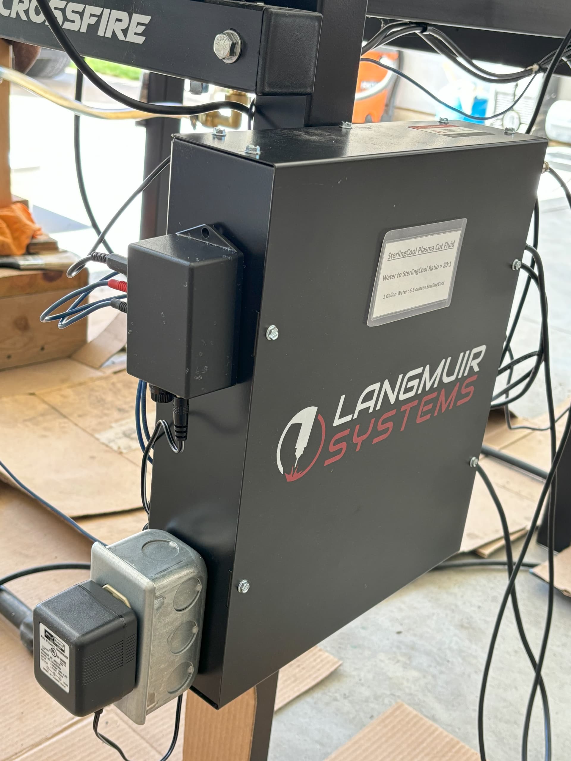
I’m attaching a few pictures of my circuit (the housing and installation) installed on my table.
So when will I get this done? If I could get it done tomorrow I would but somehow it keeps getting kicked down the line. I’m going to have to make a solid effort to get it finished.
Contact me if you’d like to stop by and see it and we’ll set up a time.