I found the following definition in the Fusion 360 documentation. “Nozzle clearance diameter - The diameter created from the initial cut when the Water, Plasma or Laser is first turned on.” I assume this is the diameter of the pierce hole. I have three questions
How does this affects cutting, e.g. how does Fusion Manufacturing utilize this parameter in creating the tool path and what happens if this parameter is incorrect?
Since the pierce diameter is influenced by the pierce delay should you use an average diameter here?
Langmuir Fusion 360 setup videos say that for Pro to use 1” for this setting…why?
I thought of the nozzle clearance diameter as being the zone around the nozzle that fusion 360 keeps the torch away from hazards while calculating tool paths.
This issue has come up because a fella that subscribes to my Youtube channel said that he was having trouble with holes, slots, etc. being undersized and that after he changed the nozzle clearance diameter to 1/16" his cut sizes are now accurate!!!
Here is the link for the fusion 360 info on the nozzle clearance diameter and from the pics in the manual the example has the nozzle clearance diameter set to twice the kerf???
That is a whole lot less than the 1" suggested by Langmuir!! You may have to copy the link and paste into your browser.
I have a hard time understanding that sentence.
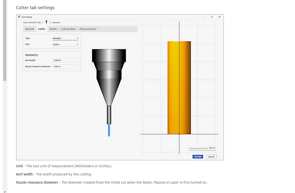
“Nozzle clearance diameter - The diameter created from the initial cut when the Water, Plasma or Laser is first turned on.”
the picture above shows the default setting as kerf as .08 and the nozzle clearance diameter as .16 .
the tip of that default waterjet is about .16 is the default drawing. the skinny part anyhow.
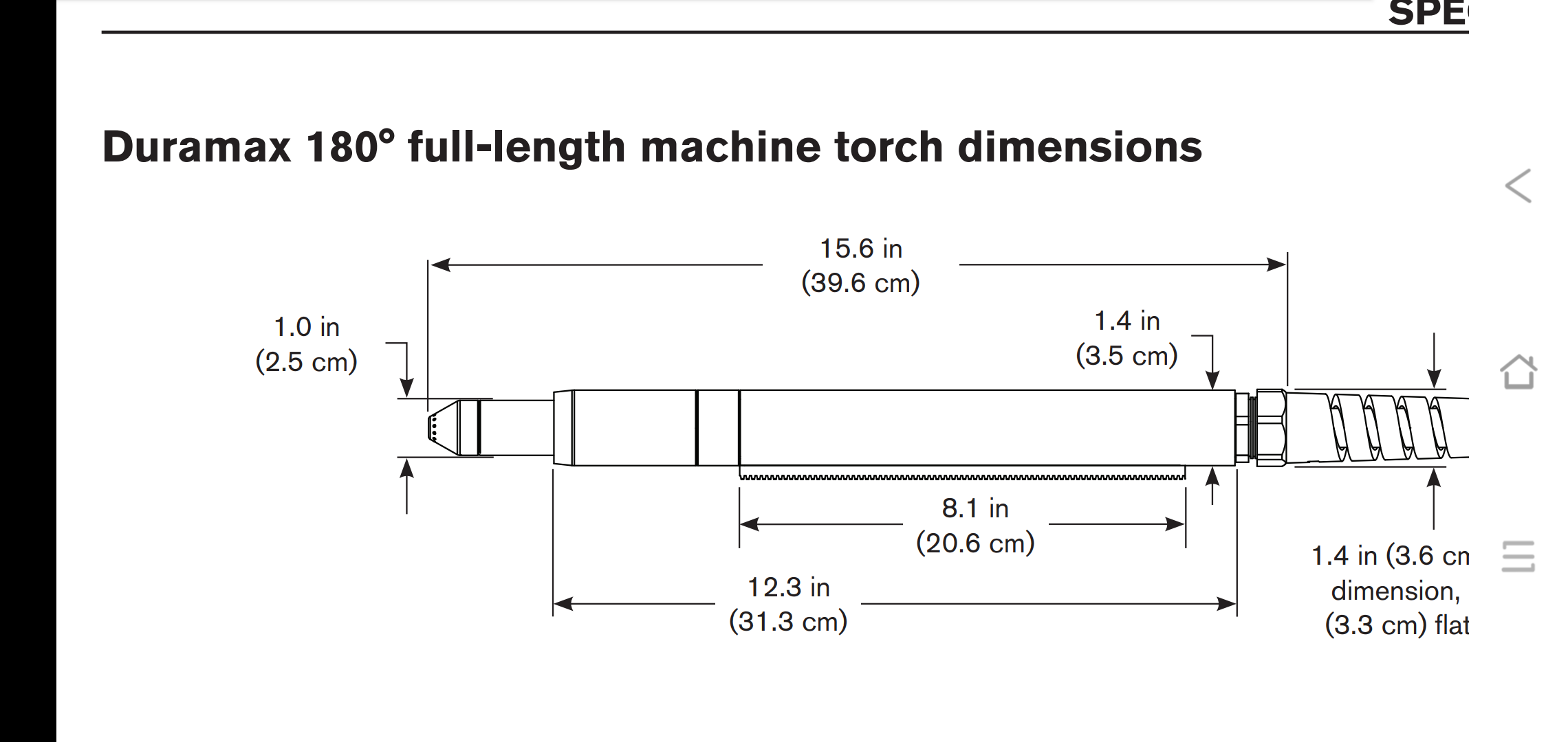
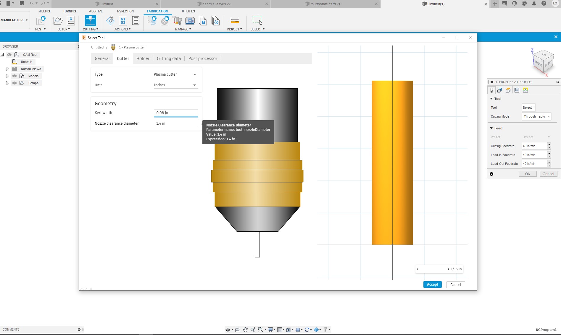
I set my to 1.4in, run almost hypertherm book setting and get very decent results.
but now i am wondering and going to have to dig some more.
Not 100%, but having done a lot of CAM work, I would guess that that nozzle clearance diameter is factored into the tool pathing. Say you have a small hole and your lead-in distance puts your start right on the main cut path. Well if your starting point for the lead-in is right on the path for the circle, but the pierce diameter is larger than your kerf, that would leave a notch in the hole you cut.
Can anyone update this? Looks like fusion 360 changed some stuff… Is “Nozzle diameter” the same as “Nozzle Clearance Diameter”. I believe they are different… but don’t know where Nozzle clearance diameter was moved to…
It’s really an unimportant variable. It seems like another holdover from milling, where something like this is necessary to prevent crashes.
At one point, fusion screwed up an update and the simulation was showing the nozzle diameter as the kerf width. People who wanted an accurate simulation had to set it to their kerf width.