Just wanted to share my experience.
I bought the table assembled from a user who only assembled the table and never used it. There were a few loose nuts and bolts, and the gantry arm leaned down REALLY hard towards the far end of the X-axis. I could also see only one side of the top bearings (inner) was riding on the steel Y-axis beam. So I started messing around with it trying to get it straight and tight.
What I ended up doing was loosening all of the bolts for the bearing supports (red aluminum blocks that hold the bearings), as well as the 8 bolts that hold the bearing plates to the gantry carriage (4 on each end). Then I lifted the far end of the gantry tube (X-axis) and propped it up. It was in a position where there was some force upward on the gantry tube. I then tightened the 8 bolts, 4 on each side of the gantry carriage. After that, I clamped opposing bearing blocks together. I used a woodworkers sliding clamp, first on the sides, and then on the top and bottom. I was hoping to put a little bit of preload onto the entire assembly, so the weight doesn’t cause sagging across the X-axis.
This helped, but it wasn’t good enough for my taste.
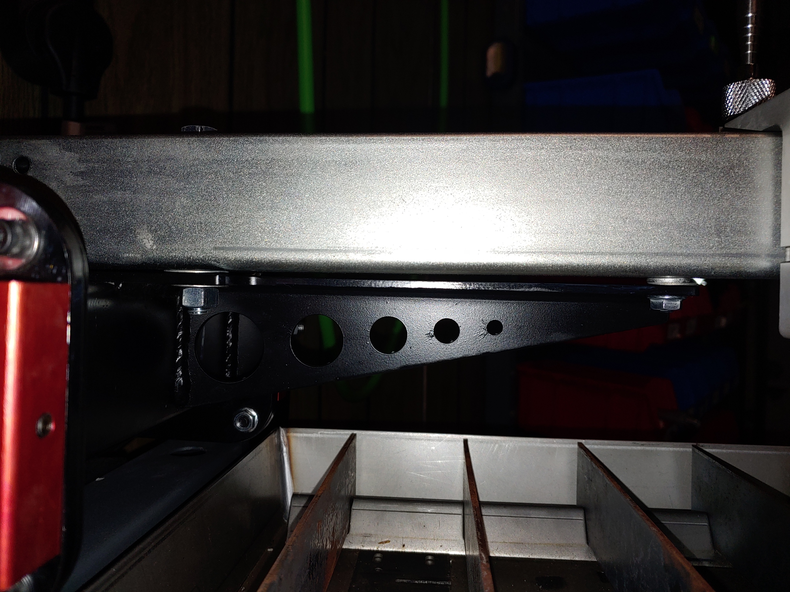
I eventually ended up shimming the gantry tube, on top of carriage arm/bracket. I think I used .07" washer on the larger bolt, and around .15" on the little hex socket head screw near the thinner part of the support arm.
This helped out quite a bit, and the X-axis varies across the entire table, but I attribute some of it to the slats, uneven slat supports, etc. I guess I’m chasing precision that just isn’t available on this type of linear motion support, and it’s probably not necessary?
I haven’t fired the torch using CNC control yet, so hopefully it’s close enough.
The Y-axis, well, I haven’t really tackled that yet.
I’ll try to keep posting as I go on to get it set up.