clamp.f3d (445.0 KB)
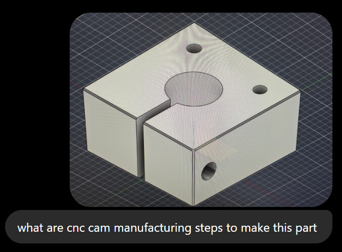
I used Claude Code driving the Fusion MCP server. After creating the design, I switched to Manufacturing then opened Claude Code with this prompt
can you create the cam operations? use 2mm oversized stock, stock is 6061 AL, use 1/4" flat end mill.
Good morning everyone,
My company recently purchased an mr1 and since I i’m already familiar with fusion 360 (I 3d print tools and fixturing
for assembly lines) I’ve been chosen to learn the new machine . The machine was purchased primarily to make parts for
pneumatic lifts for gravity flow racks . These are generally small parts made out of 6061 extruded square aluminum .
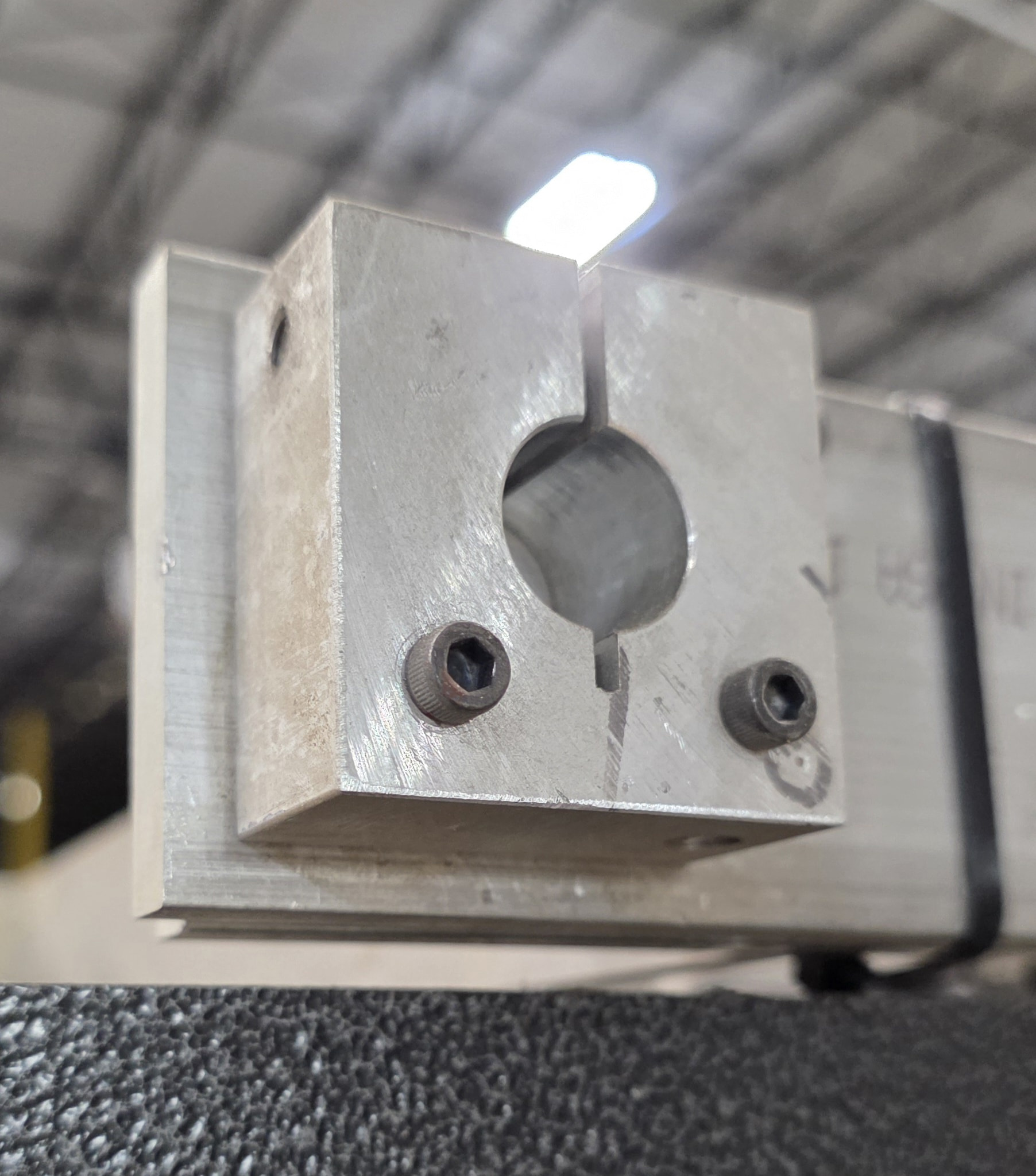
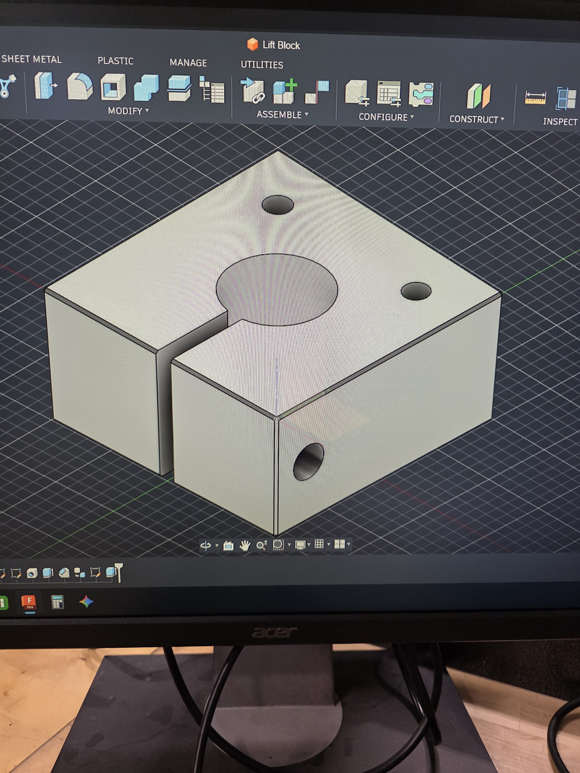
The most complex part I need to make is a block to secure a stainless steel rod (Pic attached). My first question is
how do I machine these blocks level and flat when I am cutting them from a 20 ft piece of aluminum with a bandsaw? My
second question, for now, is what is a good method of boring that Center hole? I’ve created the operation in Fusion
manufacture , but I wanted to get some feedback on whether I am using the right method and the right tools. I would
really appreciate any help / feedback. Thank you guys!
I had CC tweak a few issues after watching the cam simulation.
Here’s Claude Code’s summary
I took a crack at your clamp block in Fusion and attached the file (clamp.f3d). Here’s how I set it up. It should
cover both of your questions.
Getting it flat and square from bandsawn stock. Don’t try to use the sawn faces as references. Saw your blanks about 4
mm over in every direction and let the machine make the part square. The file uses 2 mm of extra stock on every side,
top and bottom. It’s done in two vise setups:
- Op1, top side up. Face the top flat, then rough and finish the outside profile down to 5 mm above the bottom. Rough
and finish the center bore, and mill the two 8 mm mounting holes. The bore and holes stop 0.5 mm short of the
bottom. Use parallels so the vise grips the bottom 7 mm or so of the blank.
- Op2, flipped. Clamp on the finished sides, face the bottom down to final thickness, and finish the last few
millimeters of the outside profile. Then break the bore and holes through.
Facing both sides from finished references gets you parallel faces and square sides no matter how ugly the saw cut
was.
Boring the center hole. With a 1/4" end mill, I’d use a 2D Adaptive to rough the 25 mm bore, leaving 0.2 mm on the
wall. Follow it with a full-depth 2D Contour finishing pass. A helical Bore op works great for small holes like the 8
mm ones, but on a big hole it leaves a slug in the middle. If you need a tight fit on the rod, sneak up on the size
with the wear offset or a second finishing pass, and check with a pin gauge.
Cross-bolt hole. Op3 stands the part on its side. It mills a 2 mm-deep pilot with the end mill so the drill starts on
center. Then an 8 mm jobber drill peck-drills all the way through.
The slit. I skipped it in CAM. It’s narrower than a 1/4" end mill, so just bandsaw it after machining.
One gotcha worth knowing. The slit connects the bore to the outside edge, so the part’s bottom outline runs from the
outer edge through the slit and around the bore. Pick that outline for your profile ops and Fusion can get confused
about which side to cut. Mine plunged right into the part. The fix is a simple sketch: a square the size of the part,
a bigger square outside the stock, and a circle for the bore. Point the toolpaths at the sketch instead of the model
edges. It’s all in the attached file.
Tools:
- 1/4" 3-flute carbide end mill with 1" of flute. The profile and bore run about 20 to 25 mm deep, so a standard 3/4"
flute won’t reach.
- 8 mm jobber drill for the cross hole.
The whole program runs about 14 minutes of cutting time.
Feeds and speeds are starting points only. I didn’t tune them for the MR-1. Check them against your machine and
tooling, and simulate before you cut metal.
┌────────────────┬────────────┬──────────────────────────────┐
│ Operation │ Speed │ Feed │
├────────────────┼────────────┼──────────────────────────────┤
│ Roughing │ 12,000 rpm │ 1440 mm/min, 0.6 mm stepover │
├────────────────┼────────────┼──────────────────────────────┤
│ Finishing │ 12,000 rpm │ 1000 mm/min │
├────────────────┼────────────┼──────────────────────────────┤
│ Helixing holes │ 12,000 rpm │ 600 mm/min, 0.5 mm pitch │
├────────────────┼────────────┼──────────────────────────────┤
│ Drilling │ 3200 rpm │ 480 mm/min, 4 mm pecks │
└────────────────┴────────────┴──────────────────────────────┘
Heads up: I modeled the mounting holes and cross-bolt hole at 8 mm. Check them against your print before you run it.
sorry for the formatting here.
This can be done with the $20/month plan. Using Claude desktop, you can also use the OpenAI desktop application for ChatGPT. You just need to enable the Fusion MCP server in whichever tool you’re going to go with. Claude and ChatGPT have become very adept for CAM operations. Now would I trust it with precision parts or complicated geometry? No. Should you use it as an educational tool to help you figure out what a good starting point is for you to learn Fusion manufacturing CAM operations? Yes. Either of these is an excellent tutor or teacher or instructor. Whatever you want to call it, it has infinite patience. You can sit there and have a conversation with it all afternoon and learn probably much better than watching any YouTube videos. Particularly if you have it coupled with Fusion, you can have it teach you aspects of Fusion either in the design workspace or the manufacturing workspace. They particularly work well with those two workspaces. Autodesk is putting a lot of effort into AI driving Fusion. It has an AI assistant built into Fusion. I have found that to be, frankly, quite horrible when compared to driving Fusion MCP with Claude.
One last thing - used Anthropic Opus 5.5 for this (5.5 came out yesterday and its wonderful)