New Issues Creating Toolpath on F360

Just jumping in… Could kerf size be causing F360 to drop selections?

Edit - Disregard. I just opened the F3D file.

2nd Edit - 2 Hrs later, 47% complete is all I can get with sketch selection. :frowning:

2 Likes

I know what you mean. @ds690, (or someone else with SheetCAM) would you try this DXF?
Hyde.dxf (2.0 MB)

Perhaps Casey and others are missing some update with Windows that Fusion 360 is incorporating. I have Windows 11. I believe Tin has Windows 11.

Now keep in mind, both Tin and I were able to create an acceptable g-code cut path on Fusion 360 by using the sketch selection in about 3 minutes. We were not really able to create the g-code from the body, or at least I gave up after 15 minutes.

None of our methods or suggestions are helping Casey to create the same toolpaths on his setup.

2 Likes

@ChelanJim With SheetCAM, I received 3 errors when trying the DXF. An issue regarding open paths, a problem with the drawing (upper left side trees), and a lead in problem (with the fish gills.)

This was with a .003 lead in / lead out (perpendicular) and a .054 kerf.

In other news, I’m still at 47% in F360. Perhaps it’s something n the Northern Nevada air… :frowning:

3 Likes

Thank you @ChelanJim and @Simsworx for trying,

I got it, but I had to do 5 separate 2D profiles to get there. When I tried for any more contours in a single profile than that, it would lock up on me, no matter what else I tried regarding the settings.

Fusion has been acting this way for me since the second to last update, so I’m inclined to think being on Windows 10 might have something to do with it.

But I really appreciate knowing that SheetCam struggled with it, too, because that saved me $140.

I think the open profile issues might have something to do with moving from F3D to DXF, because I can vouch that there are no open profiles. I think it’s just the amount of profiles, or edges, or whatever you want to call them.

Is there an easier way to simplify my drawings besides redrawing them? I do a lot of designs that are essentially based on adding multiple SVG’s to a sketch, and they’re always very complex.

I wish I was a better artist and could just do the stuff freehand…

4 Likes

Great job with the sign!! I want to look at it when I get a chance and watch @TinWhisperer video! I’ve been buried at work…

Sounds like we have a similar “artistic style”. :stuck_out_tongue_winking_eye:

I have been using Inkscape to assemble items into a single SVG then import it into fusion as an svg. I have no idea if it is better or worse then doing the same in fusion importing multiple sketches. I think by nature dxfs use more computing power than an SVG. @jamesdhatch explained why in a past post I read… something about splines or something or other.

I do spend a fair amount of time tuning the file in Inkscape before I bring it into Fusion so there is certainly a more efficient way to do things then how I am doing them.

One thing about Inkscape is the simplify tool is tunable so you can decide how aggressive it is each click.

I would use fusion for everything if I knew the program better but I am still learning.

Fusion getting hung up in the wheel of death is a relatively new thing for me as well so it is likely tied to an update along the way. It used to just kick out the geometry that doesn’t fit… now it seems to crash it if there is to much of it. I have had it do that when I try to use the hole from center equation sometimes.

With the help of @ChelanJim i have been able to get around that by entering a lead in radius of 175 deg vs 180 degree… maybe not related to your issue…

Maybe I’ll pull it into Inkscape and see what it looks like. I know @brownfox does similar things in affinity design. Would be interesting to see him take a crack at it.

Maybe our next forum competition. TIN vs Brownfox!?! :+1:t2::stuck_out_tongue_winking_eye:

3 Likes

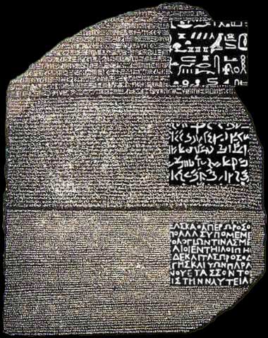
Yeah no lol but I d really do a complimentary event like the CAD CAM Rosetta Stone project I suggested in the past.

rosettastone2

4 Likes

I had no problem generating a cut file from that drawing with Sheetcam, but there are a bunch of open lines that were not offset. I took some screenshots of a few of them.

Here is the toolpaths that were generated.

This is a few of the open path errors.


5 Likes

I had no doubt, SheetCAM works awesome with dirty DXF 's and SVG’s

@ds690 how well does to generate when also applying a .05 finishing overlap and feed optimization

3 Likes

Same results with the finishing overlap(.050" overcut in Sheetcam). Instant generation of the toolpaths, even though they are open lines and therefore not offset. It can be a case of “careful what you wish for”, because it will cut everywhere there is a line.

I use “path rules” to slow down for corners, holes and small features on all of my operations, so that does the same thing as “feed optimization” in Fusion.

6 Likes

My experience says you are correct.
Until recently I had been using an old Dell core I-5. I had started using dxf files when I first learned F360 and didn’t use svg. Definitely noticed an improvement when I switched to svg. Far fewer black screen episodes in F60.

5 Likes

I can understand the couple of overshoots and double lines, as I was working so fast trying to reduce as much detail as possible on this drawing in the last 24 hours, once I started having trouble generating a tool path, I’m sure I made some mistakes. I probably sat at the computer 10 hours in the last two days trying to (frantically) figure this out. But seeing the open line surprises me, because Fusion won’t close off geometry if there’s an open line, and it was “selecting” everything just fine. And it generated a body just fine. Anyway…

I do have Inkscape, and have been trying to teach myself that program, but I’m struggling a little bit with it, and I’ve generally been more comfortable working in Fusion 360, but it’s pretty frustrating lately.

I guess I need to spend some time with Inkscape/SheetCam before I take on another one of these, because I lost my shorts on this one.

1 Like

Thanks Erik! If you look at that image of the tool path result when I tried to select the sketch profile (vs contours), you’ll see that it’s not kicking out things that don’t fit, it’s just kicking things out at random. I’m thinking it has to do with ordering. It’s finding something it doesn’t like, and kicking that out AND everything after it, perhaps?

For example the tree line had 1680 line segments in it. I found that I could not select it, and any other single piece of geometry without either having Fusion hang, or the tree line tool path get kicked out. But when I selected the tree line by itself, it generated a tool path for it in about 30 seconds.

And this is what’s been new for me after the second to last update. I used to only have trouble with the tool paths for small geometry, where it was reasonable that my lead in might actually not fit, and now it seems more related to the complexity of the part I am trying to cut.

And speaking of ordering, I’m finding that “Preserve Order” doesn’t do a darn thing, anymore, and Fusion 360 also doesn’t follow the order in which you select multiple tool paths when generating G-code. When I setup my NC file, I selected my “small details” tool path to run first, and Fusion reset the order to the first tool path I had generated.

Minor frustrations, really, and now that I know how to work around them they are manageable, but I wish I could pinpoint the issues, beyond maybe just accepting that converting multiple SVG’s into a large DXF file can overwhelm F360 (on an older computer).

2 Likes

Having the same problem here on my end ever since the update non-stop problems with creating cut paths that I have cut before with no problem. Been doing this for 5 years and never had this bad of an issue. Has to do with the software update I have not changed anything. What is the fix?

1 Like

Logos by Nick on YouTube has a great series of videos on Inkscape. It’s not plasma specific, but you can learn how all the various tools work.

4 Likes

Thanks Dave. I think I’ve seen a couple of his. I’m not sure why I’m struggling so much with this one. Of course, I could never figure out Illustrator, either. And I always had an easy time with AutoCAD. Must be like a Left Brain/Right Brain thing…

1 Like

I just had a minor epiphany. I was working on a toolpath for another design that I drew completely from scratch, with a lot of small geometry, and I couldn’t get Fusion to select any of the geometry no matter what I tried. And then, after lowering my finishing overlap to 0, it started picking up ALL of the small geometry.

The thing is, the squares I was trying to select were roughly 1/4"x1/4", so I knew that 0.050" overlap that my plasma likes wasn’t the issue. And then I went through and manually selected the lead in position on every single hole, and bada-bing, it picked up ALL of them.

Now, I can’t comprehend why Fusion can’t seem to pick a lead in position on a 0.250" line that leaves it enough room for a 0.050" finishing overlap anymore, but telling it to start towards the bottom of the line gave it the confidence that it had been previously lacking. And to be honest, I didn’t even know that you could pick multiple lead in positions.

So, I guess I’ll just add that tedious step to my work flow until I can find the time to learn SheetCam.

What a trip!

1 Like

That is what I was finding with lead-ins of 0.03 with a 45 or 90 degree approach.

But I could do a radius of 0.03 at 170 degrees, and I swear that is a much longer route, and it would take it. If I used any additional lead-in distance, it was questionable results. Perhaps a different lead in, could spare the need of the 0.05 finishing overlap. You might be able to use an overlap of 0.01 or 0.015.

Glad you had…some success. Epiphanies made the light bulb and the telephone!

Make us a new light bulb Crazy Casey!

2 Likes

SheetCam is easy to learn, in under an hour you will have sheetCam figured out.

2 Likes

If you ever need to go that small with a lead-in/out, you should just go with none. That’s not practically doable by the machine and will only cause a slight stutter (probably not visible though) in the motion path the machine takes. With the perpendicular lead it has to stop to change direction. With some kind of sweeping angle it can adjust the motion path to slide into the cut line. These settings are still going to lead to a divot at the beginning & end of the cut so might as well save the computer some complex calculations by just skipping the leads.

2 Likes

@jamesdhatch Agreed. Typically, I’ll use a 60 degree radius lead-in, occasionally up to 150 degree, depending on what I’m cutting. The .003 was a mis-entry. I had intended to use .03.

2 Likes