Brand new crossfire pro
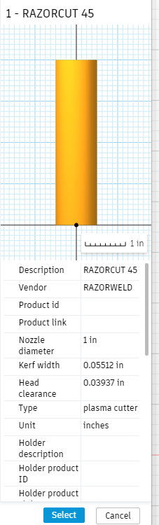
Razor cut 45
THC
Fusion 360 CAD/CAM
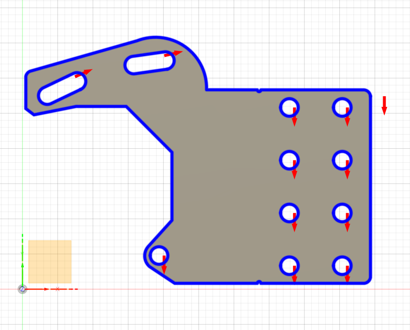
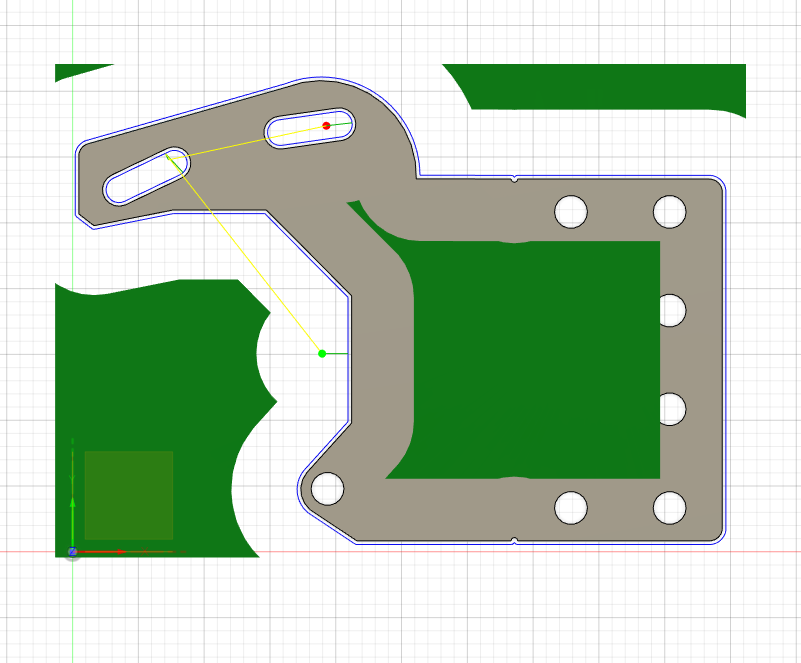
Short version of the question. When I program toolpaths on some inner geometries why do the arrows disappear when I save the path. Not from all of them just some.
If I have learned anything from poking around the forum it is that you all like details. Unfortunately, I don’t even know where to start.
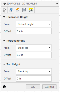
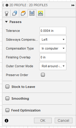
I will post a picture (if I can figure that out) or two of some settings and see if I give you the info you need to help.
Fusions 360 discarded those holes because when it added up your kerf width, lead in, lead out, pierce Clearance, lead in radius added up to more than what it figured it could fit in that hole.
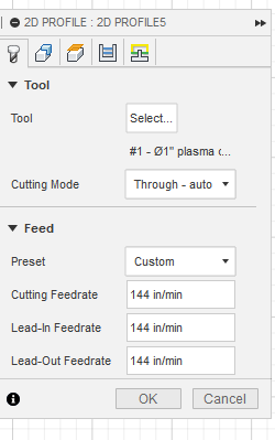
I would consider your lead in angle about 60 to start.
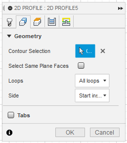
Try to reduce your lead in to the point that it includes those holes in the tool path.
One other thing that fusion’s been doing since the last update is that instead of applying the kerf width to the simulation it’s applying the nozzle diameter that’s why there’s such a wide swath taken out of that green. It doesn’t affect the G-Code it uses the applied kerf width but it does mess up the visual. Hopefully they’ll correct that in the next update it used to work perfect.