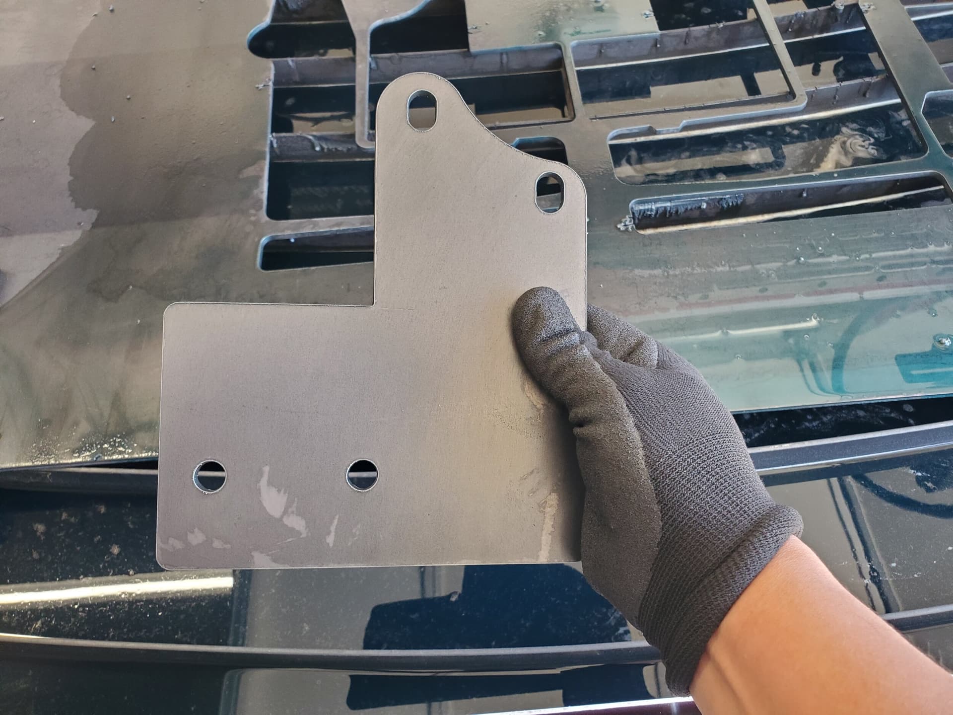
I am having a difficult time in being able to extrude shapes after I have created flanges on my original sketch. I have watched several videos on YouTube and despite my efforts, I am not YouTube certified.
I was able to create and extrude on the original sketch, but after I created a flange and flattened it to sketch the shape that I need to be cut out - epic fail. It looks like the shape I drew is on a different plane (same plane as when it was flattened).
Please help. I have another flange that I need to do on the opposite side that will have holes similar to the bottom. I believe that if you all can help me understand what I am doing wrong, I will be able to handle the other side.
Taking a 2D item, and creating a flange (and adding bends) is different than creating a face in the Sheet Metal section and adding flanges to that.
The former will shorten your flange length as some of it is taken up by the bend radius vs having the appropriate sizing when drawn in the latter form.
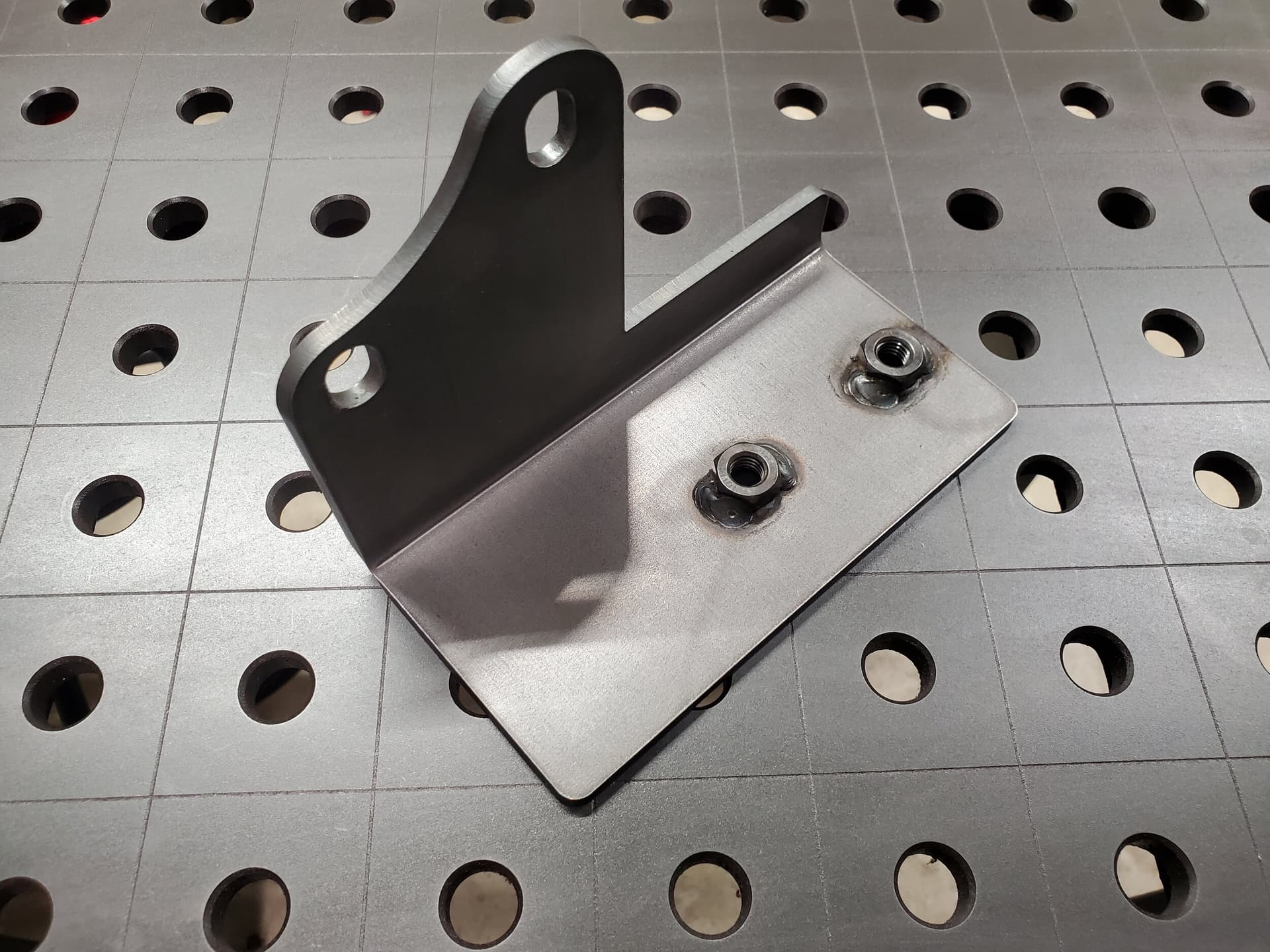
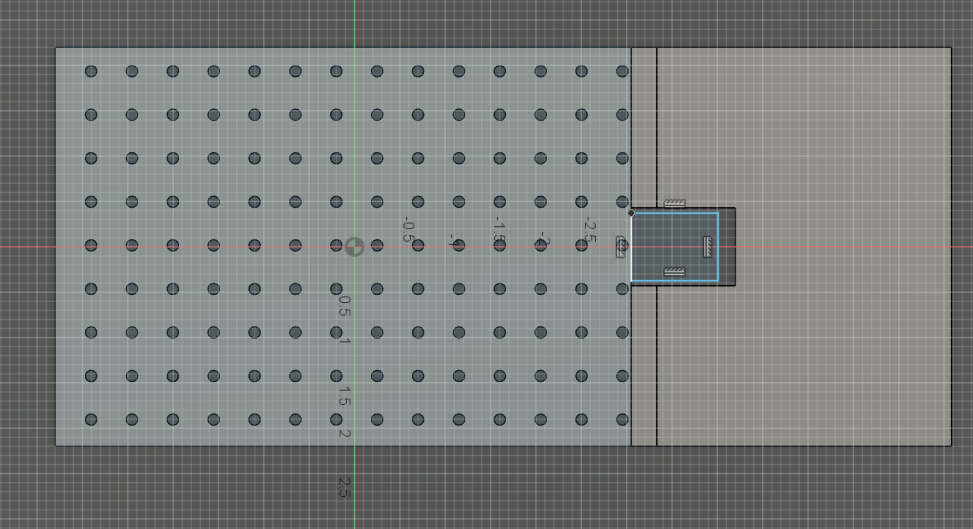
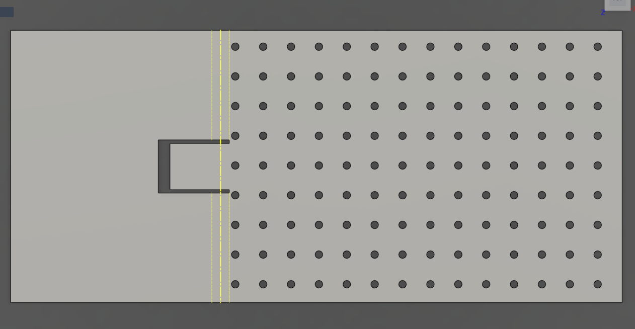
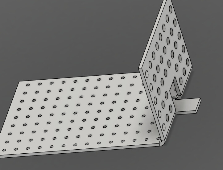
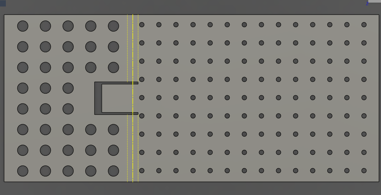
That “tab” needs to be cut out of the vertical leg of the bend. I assume it shows up the way it does because I drew it after I unfolded it. For the life of me, I’m unable to figure out how to extrude (cut out) shapes in a sheet metal body.
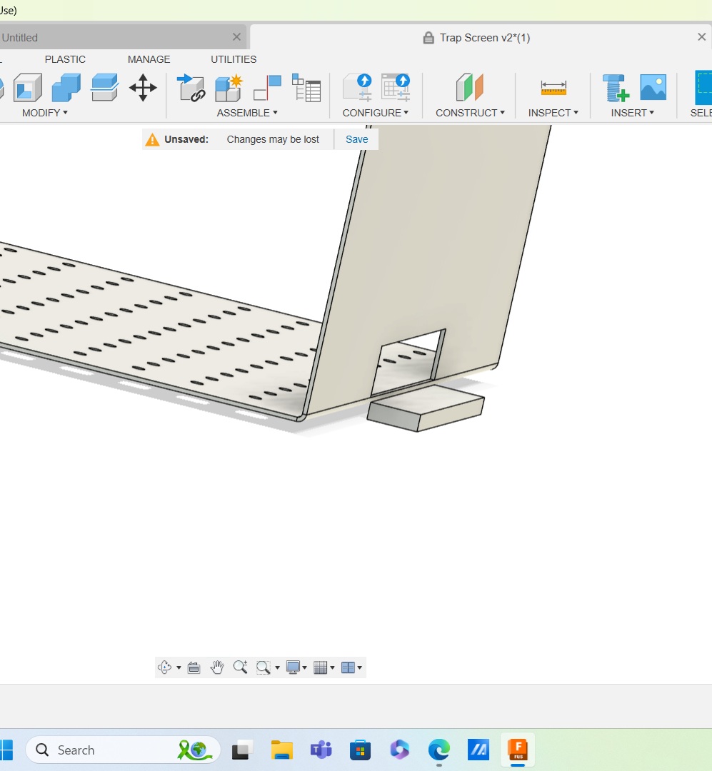
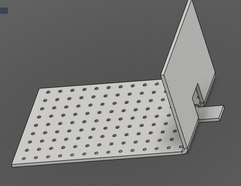
I rarely use Sheetmetal functions, but is this what you are trying to do? I left your original box and Extruded it just to show the result, but I added a new sketch and Extruded it about where your other one is, except on the plane I believe you want it on.
I think you are correct in what went wrong. Just don’t unfold, click to start a new sketch, chose the plane for the “upright” side of your drawing, sketch the rectangle (1.5 x 7.5), double click on one of the borders to select it, then hit “E” for extrude, click in the box and enter a negative number to extrude it back through your upright face.
It is true that you can do all of that in the “Flat panel” perspective but you will not be able to see the 3D representation of what you do in the “Flat panel” environment.
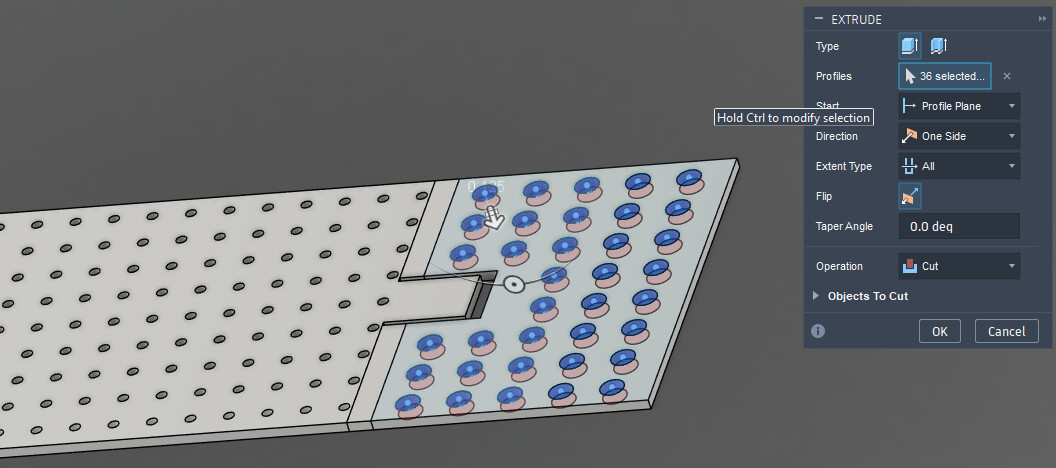
To add the holes on the flange, do the sketch in the “Unfolded” position. Extrude cut and you should be golden.
Thanks for the guidance fellas. To be clear, I should rotate the drawing to the side (plane) that I want to modify and create the new sketch there instead of unfolding and making the modifications (extrusions)?
This is where I ran into issues. When I attempted to extrude the rectangle (while in the flat pattern) I received an error and Fusion wouldn’t allow it. When I refolded it, the rectangle showed up on the same plan as when it was unfolded.
I really need to take a good course on Fusion to understand it better……
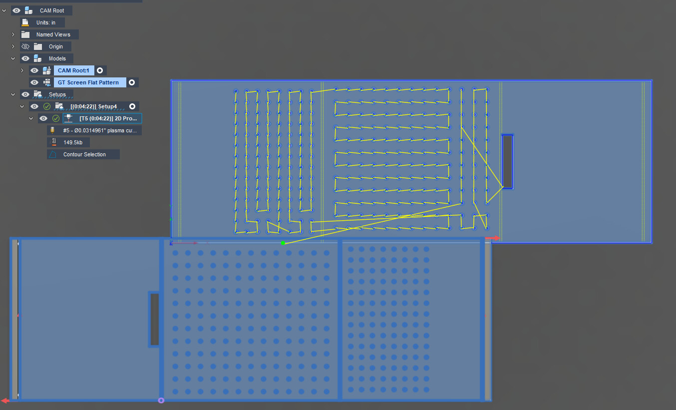
When I go into CAM, it looks like my settings are having the bend lines cut. If I don’t select all of the faces, it doesn’t cut the outline of the file.
Calling in for another ask here, what am i doing wrong?
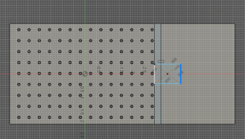
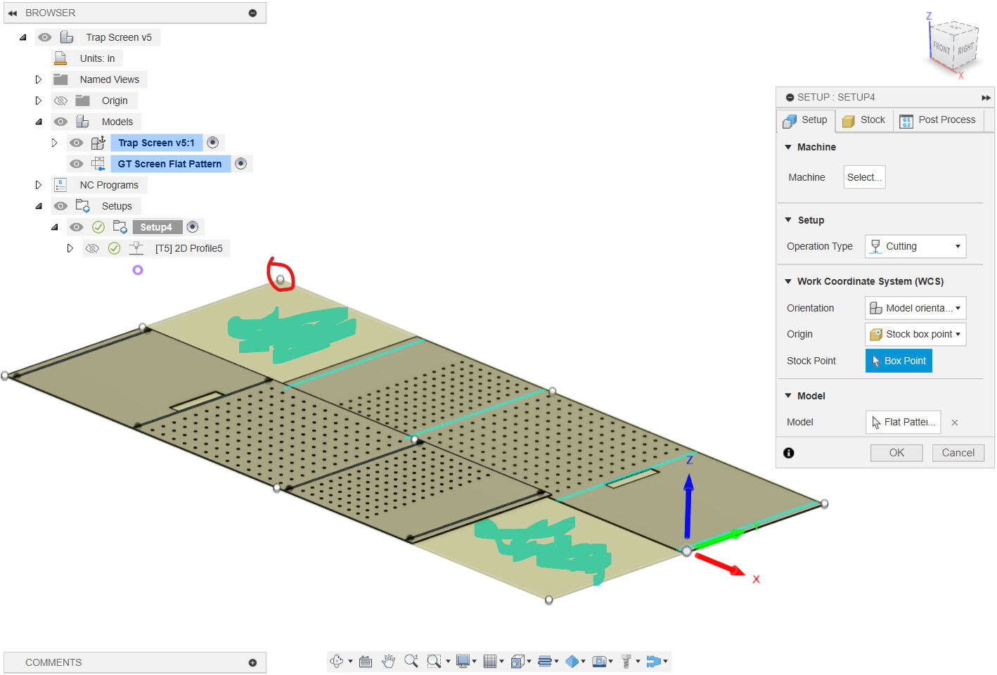
Yep. You were cutting out the panels because it was looking at the body. Direct the SetUp and the toolpath to the Flat Pattern. It behaves like the body in manufacturing:
Thanks Jim. I was able to modify my file (with your guidance).
Why is the view on my setup different than yours? The upper box point of the flat pattern is all the way up in an unused area of the drawing (shaded blue). How in the heck did I create that so I know what not do do in the future. It worked out, I just chose the lower box point.