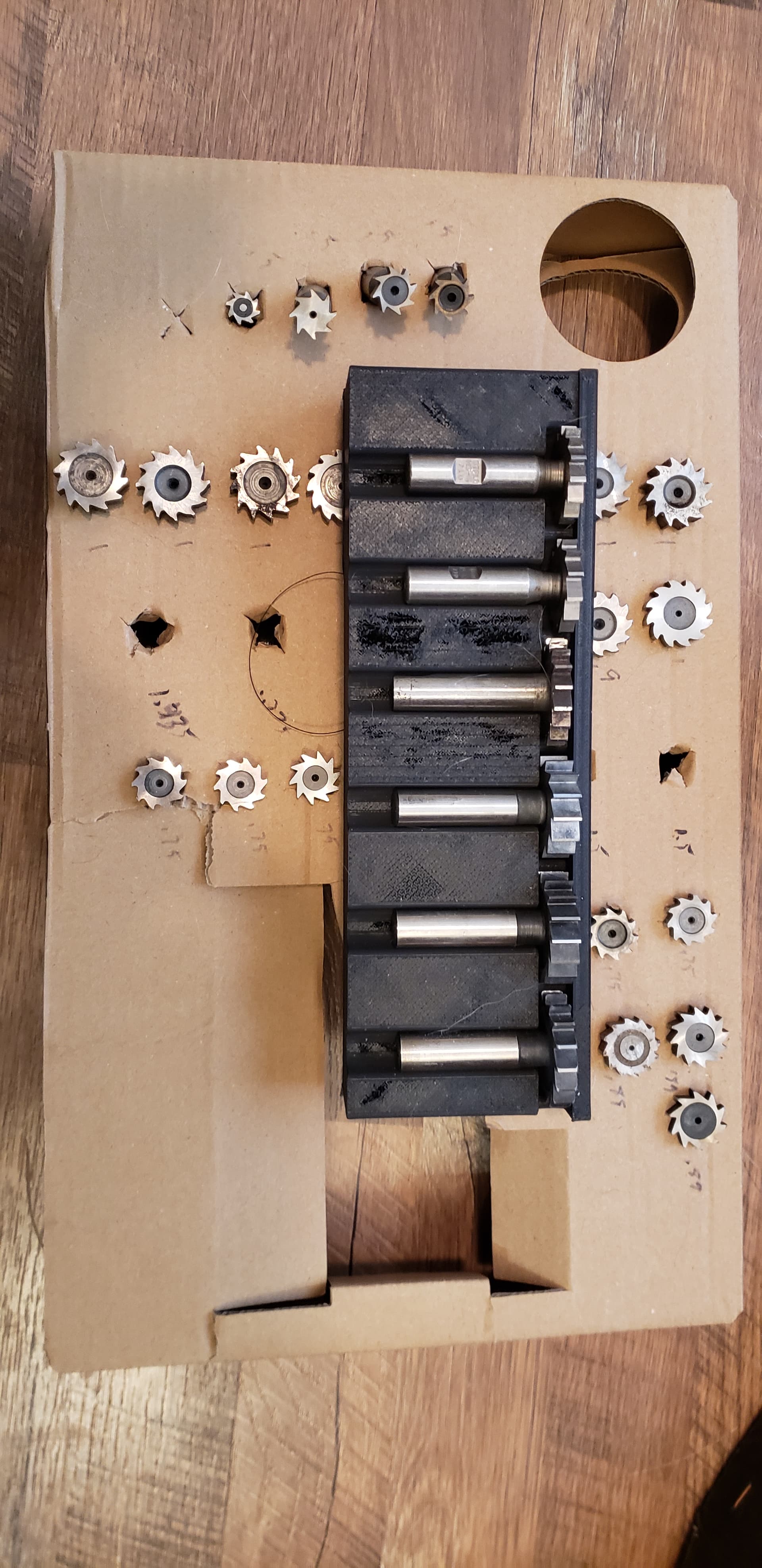
I am trying to design a tray for my slot cutting bits - 32 of them. These will be 3D printed.
I want to do them laying down to take up less space.
Sizes are .5 to 1.5 od, .062 to .375 depth of cut, 2.5 OAL.
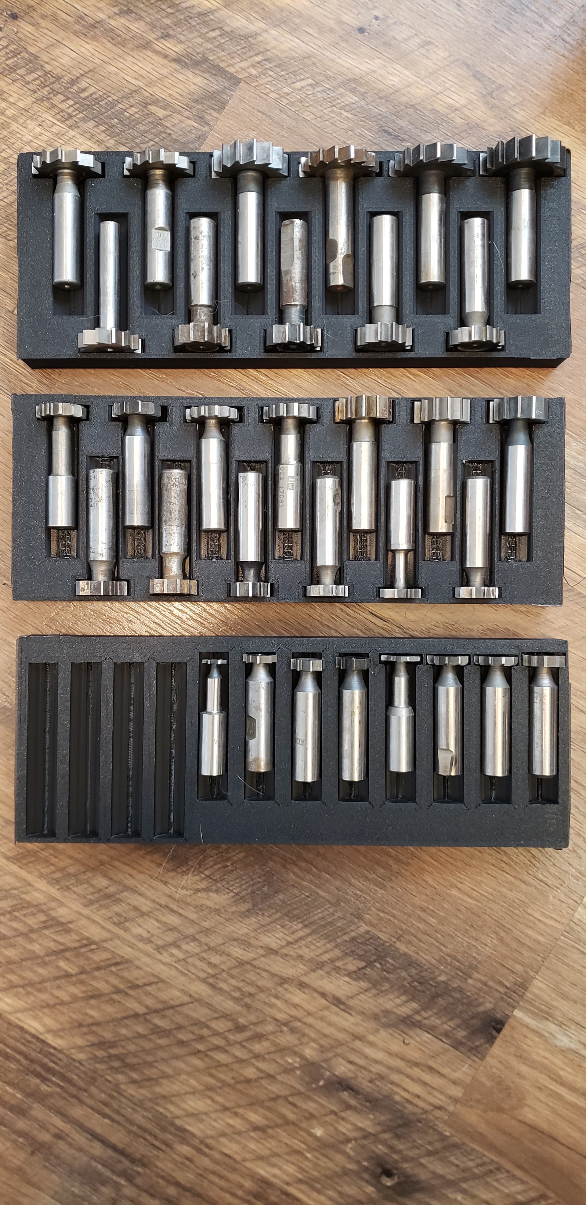
Here is a prototype that I made. Yes it looks like crap, but it was supposed to be a fast print to test and 2% infil does not leave much for overhangs, and I stopped it at the start of the second top layer.
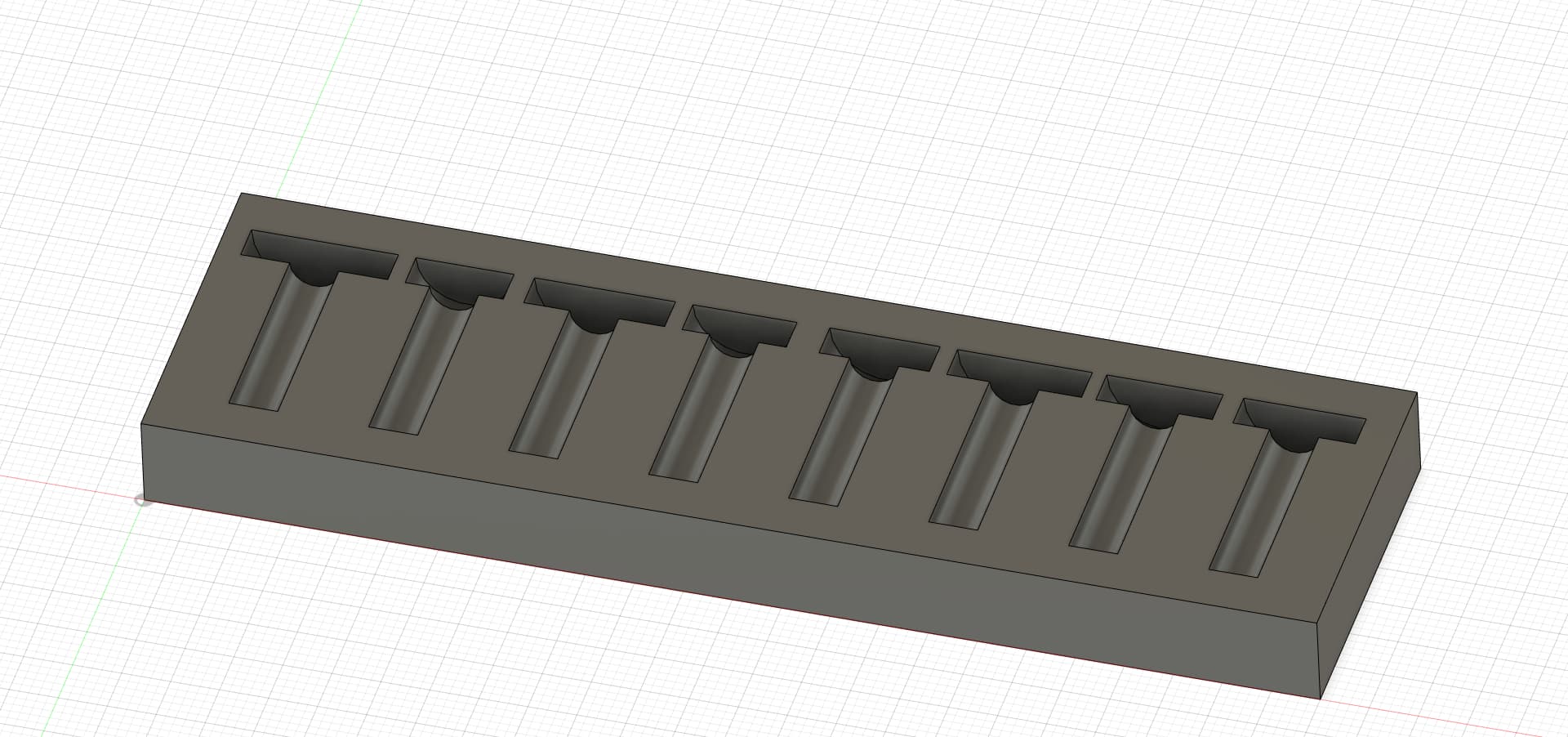
Extrude a rectangle that is thicker than your widest cutter (1.5" i believe), 1" wider than your shank length (2.5"?) and I arbitrarily chose 12" long.
Create an offset plane from one edge. Sketch a single shank (1/2" Diam ?) half-way into the rectangle. Extrude / Cut for length of shank. Should produce a single half-round cutout. Pattern than feature along the length of the rectangle. (I chose 8 times.)
Create another sketch on one of the half-round faces. Turn the view cube so you can see the other (opposite side) half-rounds. Project the half-rounds to your current sketch. Re-rotate back to your sketch and draw your cutter as circles at the top, using cutter diameters, alternating a large one with a small one. Close sketch and extrude / cut, by the thickest slot cutter width. (I used .375")
The Offset plane could just as easily been to set an offset in the extrude window. (And create the sketch on the outer face.)
Projection is nice in that it brings outside faces from features onto your sketch plane. And they will change if the feature changes. (For example, if you decide to change spacing on your pattern.)
Good luck!
Edit - Disclaimer - I currently use Fusion 4-6 hrs daily. Prior to that, aprox 10 years of 3D design using Inventor / Solidworks. Fusion can be a bear to learn, but I find it’s more than capable.
@Simsworx - Thanks to your direction, I was able to get the first row done.
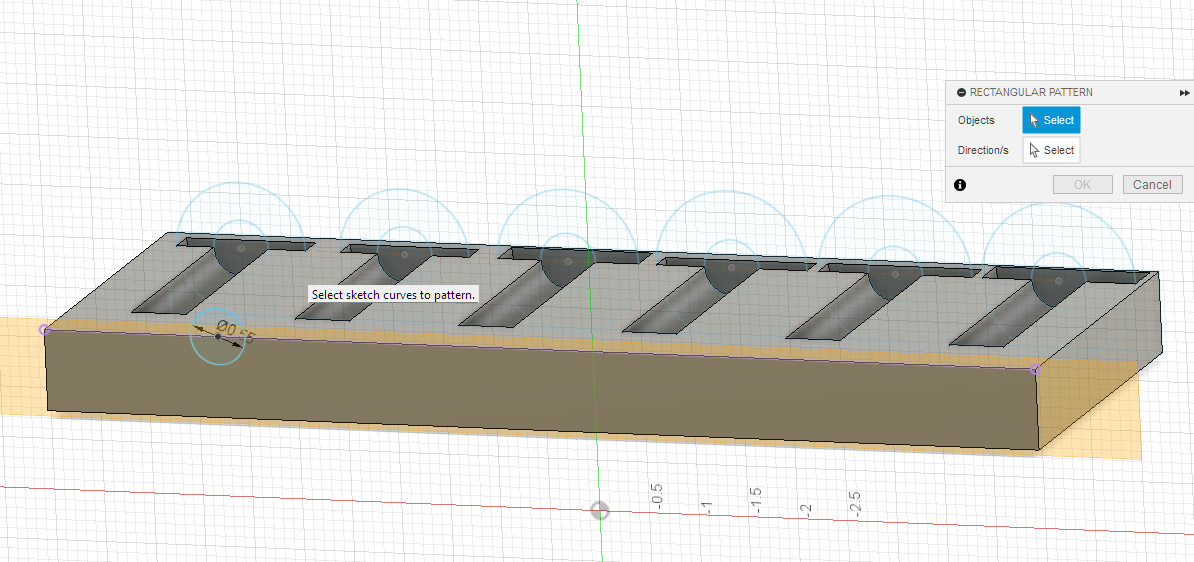
Now I am fighting getting the second row done on the back. I can get the offset plane done, but when I draw the first shank circle, the try to pattern it across, I can’t get the pattern tool to select it. It is demanding an object. I am pretty sure I am following the same thing I did on the first side.
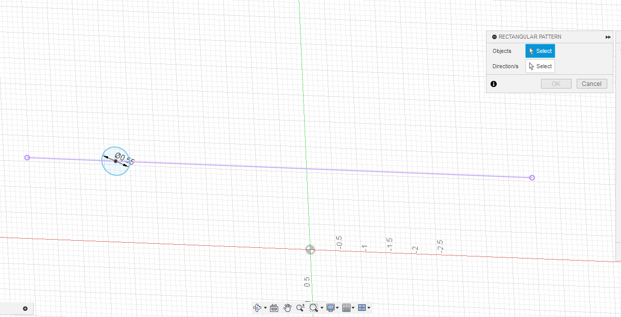
Go ahead and extrude / cut the circle 1st. Turn off visibility of the body (click the eye icon) to allow selection of the half-circle embedded in the block. Once extruded, pattern the feature as opposed to patterning in the sketch.
Took me 5 more attempts, turn out that I was having trouble selecting the offset plane on the backside as my sketch base. Once I finally got it, then I could get it to select my circle as the pattern.
Would not have found that if I had not done the extrusion. Seeing them coming off the back face instead of .1 inside was the clue.