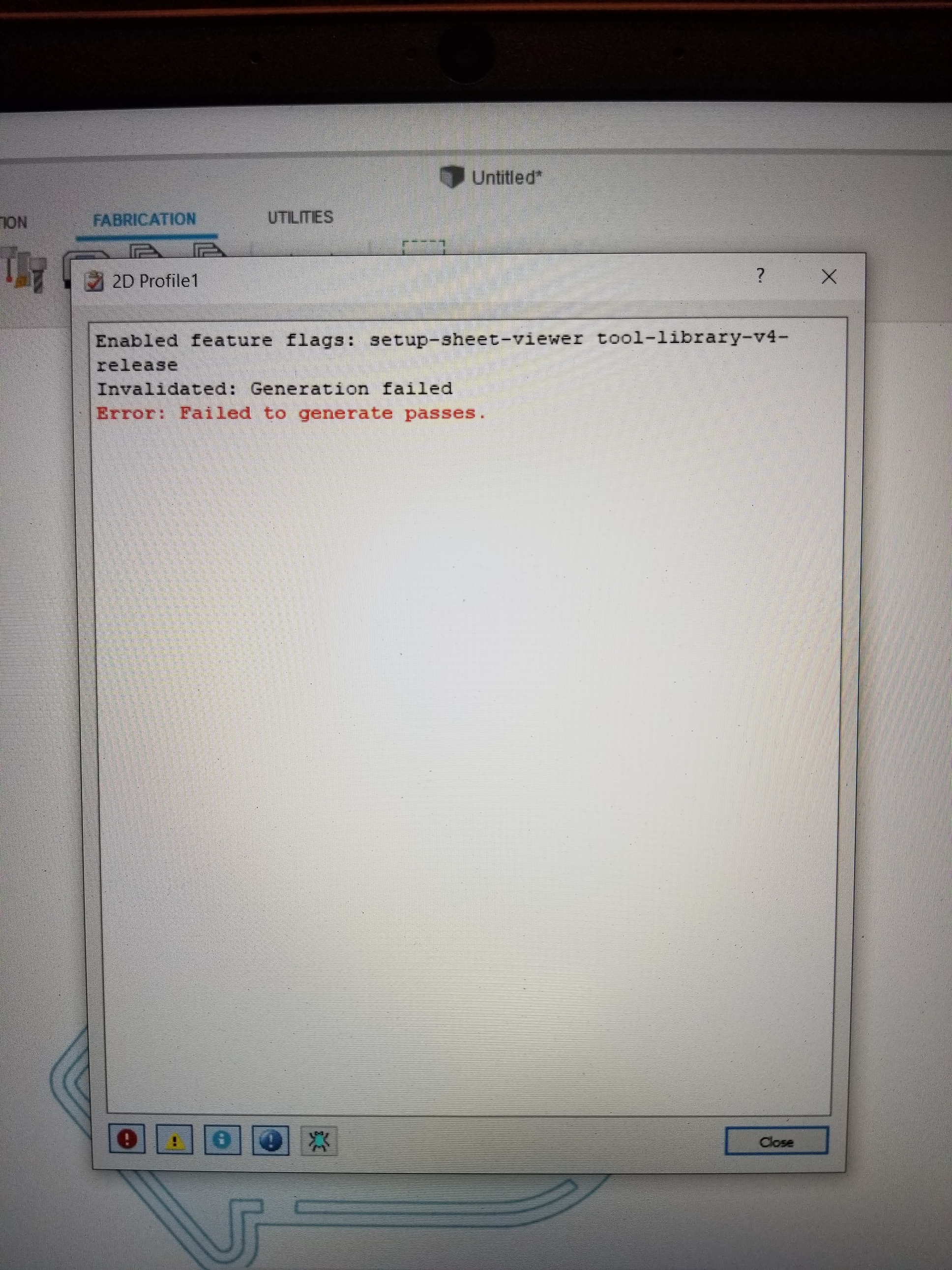
II keep getting a error failed to generate passes. When I hit ok it stops at 9% and gives me an error. What am I doing wrong
welcome to the forums…
we do need a little more information to help you…it is like going to the doctor and saying “i’m sick…what is wrong with me Doc?”
what table are you on…crossfire or the Pro?
are you running Mach 3 or fire control?
what software are you using for design and post processing?
what error are you getting…? is there a screen shot of the error we can see?
Crossfire pro with fire control. I use fusion 360 for design and processing. until now I’ve only cut a few small simple parts. I purchased a dxf of a sign to try something different. I had to scale it down some. When creating the 2d profile i get an error saying failed to generate passes.
How much did you scale it down?
In the passes tab switch it to roll around corners. That might fix your problem and if not you’ll have to go through it and look for areas that interfere with your kerf width.
I agree with Fortifyfabworks, but check for broken lines and small segments that could be missed. I have down loaded dxf files and had the same problem. Turned out to be broken lines and usually at the end of a radius along with real short segments.
I purchased a dxf. When I pulled it up in fusion the sign was 189 x 304 inches. I kept scaling it down to about 28 x 18 inches. I am very new to this with no computer experience. I wasn’t sure why the sign woul be that large to start with. Maybe did something wrong scaling it down. How do I check for broken lines. Also should I be cutting all cut in one profile or multiple cuts.
When you select a line to cut it should highlight the whole line. If you have to select multiple parts of a single outline then there is a broken line or a line the overlaps and runs long in the contour.
The sign was probably made in mm that’s why it opened so big.
If you put up the file I could take a look or just a screen shot of it.
1 Like
As far I remember all lines were highlighted completely but I’ll have to recheck when I get home. I tried to convert to mm but it measured 7700 or so mm’s. When I get home I’ll post the file. If it’s in mm do I have to keep it that way or what should I have done.
No it doesn’t matter what it is just scale it the size you want like you did.
This is the file I’m trying to cut. All the lines look ok to me but then again really dont know what I’m looking for.
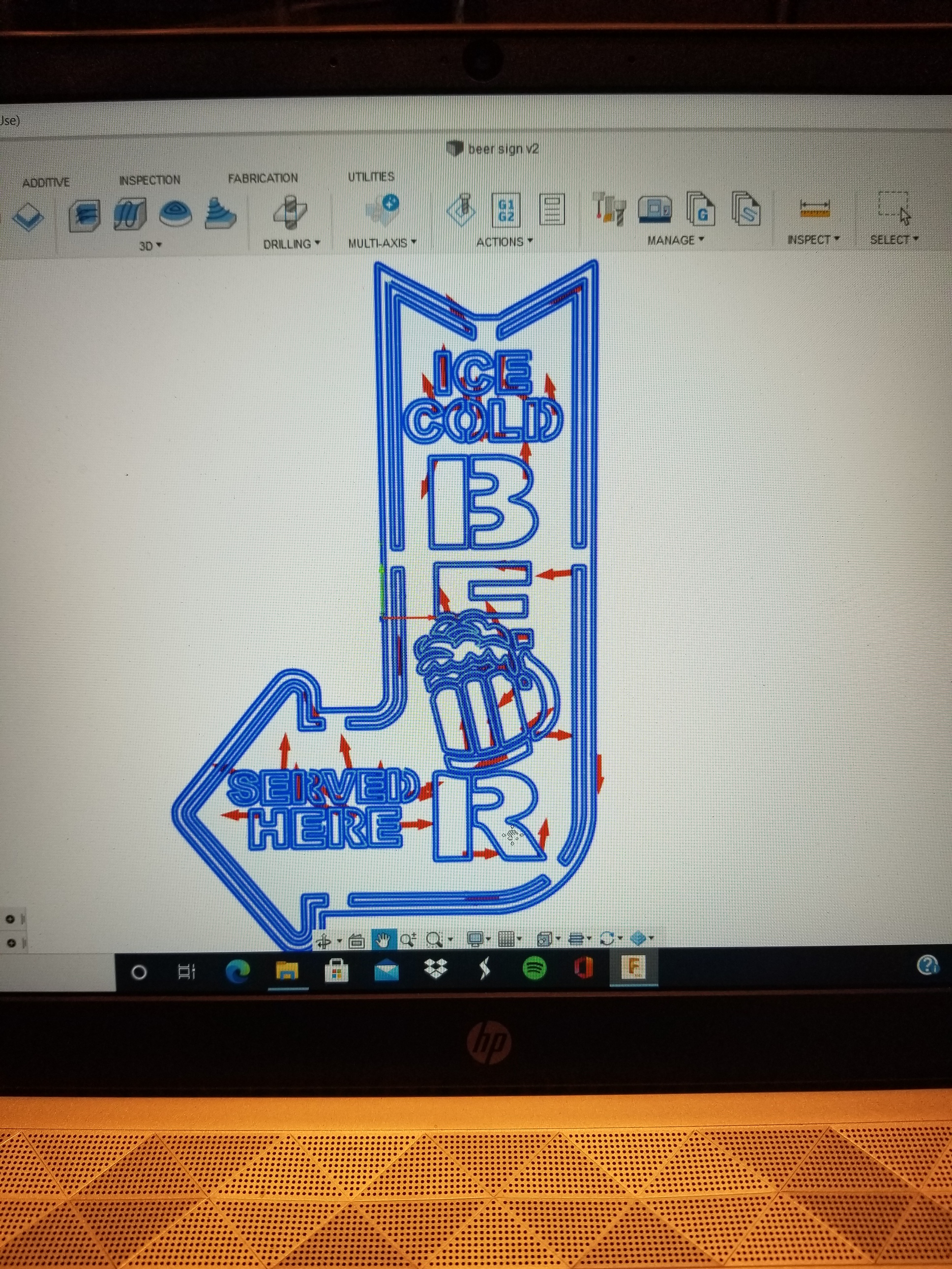
Its hard to tell with just a picture for clearances and how wide some things are but does it not generate anything it just gives you that error message?
This might be a little low level, but I’m a software guy. Make sure you’ve got a backup copy before trying this.
You should be able to open the dxf file with notepad then search for units and change to mm, that would scale you 25.4::1
$INSUNITS
70
1
9
also measurement
$MEASUREMENT
70
1
9
change the 1 to a 4, that’s from inches to mm. There are a bunch of different unit specifiers, so check them all. I don’t know if this will help, but it will avoid weird software scaling artifacts. That will get you around 7.4"x12". I’d guess that scaling up is probably easier for the software than scaling down, less likely to generate artifacts.
Here is the spec I got that from:
I tried on a random simple file and it didn’t break it. Your mileage may vary.
1 Like
When I zoom in all lines are complete. once I enter everything in the 2d profile I hit ok it gets to 9% everytime then gives the error. It only gives the error but doesn’t tell me what’s causing the problem. should I try starting over and just leaving it in mm. I had to really scale it down alot to get it to where I wanted it.
Have you changed it to roll around corners in the passes tab?
It seems like fusion likes that now since it brought it out on whatever update it was for this art type stuff.
I wouldn’t worry about inches or mm just work with whatever you normally work in. Also you don’t have any open lines or rogue lines if when you select the contour it selects the whole contour so I don’t think that is your problem either.
If changing it to rolling around corners doesn’t generate a tool path just try setting the sideways compensation to center and shut off lead in and lead out and set pierce clearance to 0 and see if it will generate a path that way.
Here is a similar file that I know works if you want to try it.
Ice cold beer.dxf (785.9 KB)
I changed it to roll around corners like you said. It’s gotten farther than it ever has. It’s at 28.9% does it normally take a while to generate a toolpath.
I was just looking at the design that you are working on! It looks like there is a segment missing on the top left on the inside point and on the E in ice. There is another segment missing on R and the D in SERVED. It looks like a segment is missing in the head of the mug of beer. I zoomed in as close as I could, it looks like they are missing but may not be ? I could be wrong…
Some things will take a a minute or so if there is a lot of lines and depending on your computer but normally pretty quick.
Fusion requires a lot of computer resources to generate tool paths. A quick check to see if that’s the problem, is to break your toolpath into parts. Keep them all in the same setup and they’ll all generate together into one tap file.
Since I usually have different lead-in/out values for different sized cutouts I would generally create toolpaths based on the cutout size -sm, med, lg.
With fewer lines & therefore motion paths to calculate in each path, Fusion is able to generate them easier.
1 Like