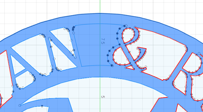
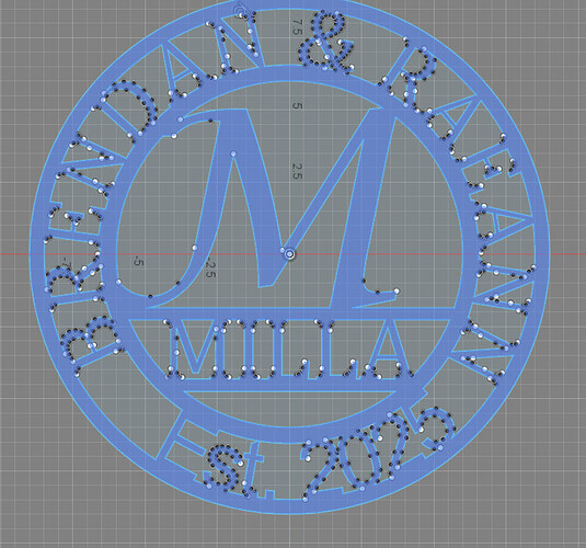
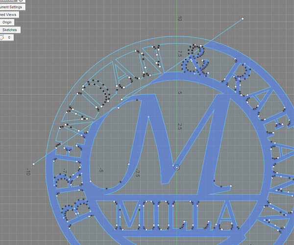
Hi - first post ever from new user. I’ve been working on Monogram and having trouble with a small section not showing cutout. Have not been able to get the area between the “N” and “&” to show a cutout so suspect that metal will remain when I cut on table. I don’t see any opening in perimeter so not sure why or what to do about it. Thx
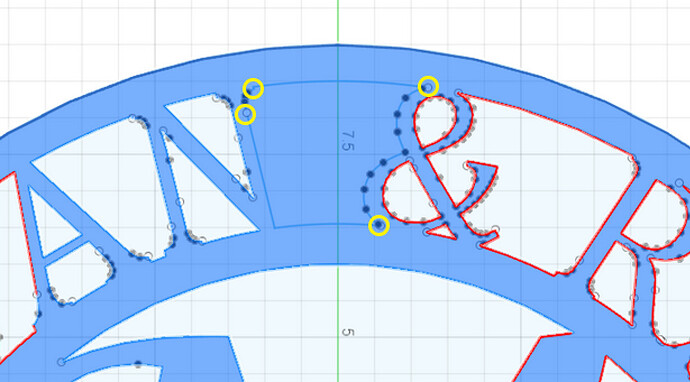
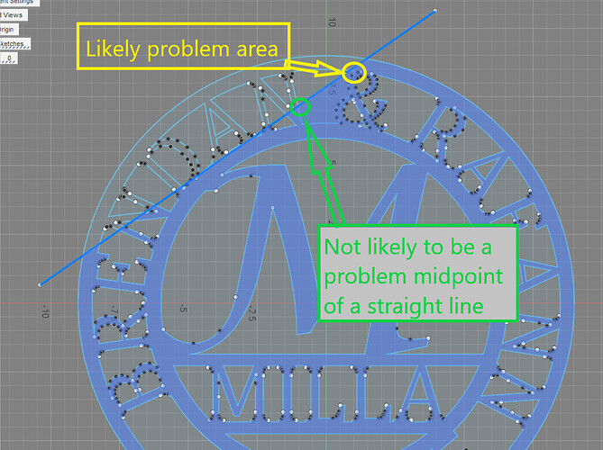
If you shared your f3d file, it would be easy to say. Not having the file it is likely one of this 4 spots, marked in yellow:
It is either two lines that don’t perfectly coincide or a line that extends past the one point or a double line segment. Double click on a line in that contour and see where it stops. Zoom in on it. You might need to delete a segment on one side or the other of where the segment selection stops. Redraw that deleted segment. Keep repeating the process until a double click selects the entire contour.
BR Monogram v0.f3d (224.9 KB)
Think this is f3d file…
Ok but HOW did you do that! Like to know so I don’t have to bug people going forward… Like to be self sufficient. Thx
The issues were depicted in your drawing like @ChelanJim pointed out
The white dots
First I deleted this line and redrew it:
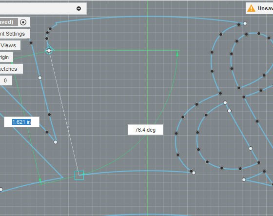
Notice the white dots are gone:
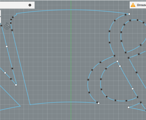
Then I deleted and redrew this segment:
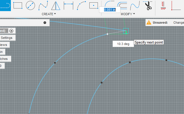
White dot gone:
Those were the only two changes. Notice there are still some white dots but they aren’t causing a problem. I just used the double click method to find where the selection of segments stopped.
Great - Thank you. I didn’t realize there was a difference between the color of the dots and their impact.
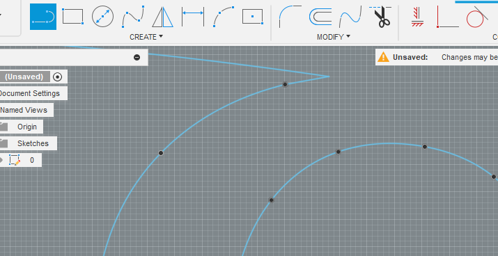
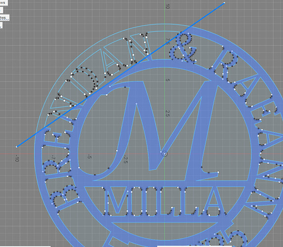
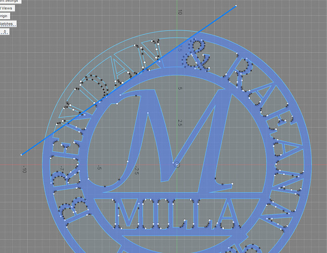
In more complex drawings the “divide and conquer” method is helpful. You kind of develop your own styles as you encounter and resolve issues. Just to briefly show that, we could use your same example. You draw a line or two across your image then you monitor the profile as you move the line. The profile is good when the line isolates you from the problem area. As soon as you go past a problem area, you will see the profile mess up:
As soon as that line went past that right upper corner of our problem area, the problem is revealed.
Good way to troubleshoot. Thx
So the white dots signify what? An unattached anchor point or? The reason I ask is because there are a lot of other white dots.
The line method of finding the problem area is awesome, thanks for sharing the little tidbit.
This is an AI answer. Keep in mind that not every “white” dot will mess you up but it is likely the problem area when you can’t get the sketch to behave normally with “Profile” selection and manufacturing.
In Autodesk Fusion 360, a white dot in a sketch indicates an unconstrained point:
- Explanation
White dots appear when the end points of lines or splines are not constrained to other geometry.
Here are some other colors and their meanings in Fusion 360 sketches:
- Black dot: A stacked constrained point of two or more geometries
- Purple/Lavender: Projected geometry
- Green: Fix/Unfix geometry
- Black (or white if the environment is dark): Fully constrained geometry
- Orange dashed: Construction line
- Blue: Unconstrained geometry
- Yellow: Failed projected geometry
