We have a Miller Spectrum 875 (NOT the auto-line version) we were planning on using with our soon-to-be-delivered CrossFire Pro and the torch height controller. I’ve read through the THC wiring instructions and wondered if others can confirm what I’ve found.
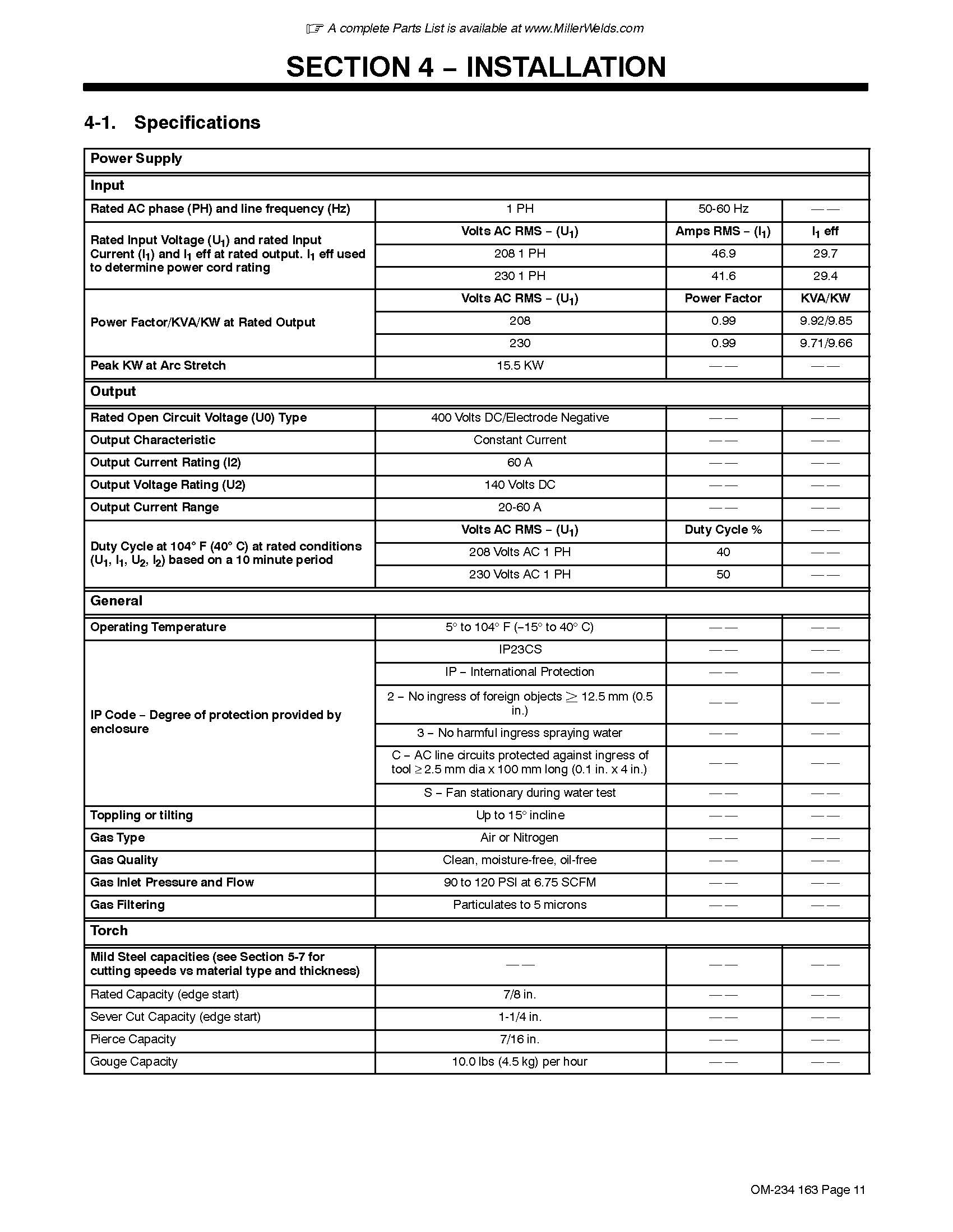
According to the Miller user manual, the rated open circuit voltage is 400V, which is greater than the 300V max listed in the THC manual.
Here’s my question - have I read this correctly? There is also an output voltage rating of 140V listed in the specs. Is this the value I use?
Assuming the 400V value is correct, can we still use the THC but just not turn the voltage too high? Or does anybody on this forum know if there is a divided voltage available on the machine somewhere?
The Output Voltage Rating 140V DC (V volts not A amps typo) is the voltage you care about for THC. The 400v DC OCV is the voltage in the ‘air’ when it’s live but not doing anything. The THC will take the 140v down 50:1 for the height calculations. I think you’ll be using the raw voltage connections on the voltage divider for this machine. I’m using a 625 miller that has the 50:1 built in. All that said, may not be a bad idea to check with LS support to be sure.
I have the same unit and have the THC coming in as well. I am gonna need to know how to hook it up also. I did call Miller support and they told me that this unit does not have a 50:1 voltage divider nor do they sell a kit for this unit. He did mention that there maybe an aftermarket part that I can get and would not recommend any but no luck yet. Any information would be greatly appreciated. Thanks in advance.
Miller’s web site isn’t responding as I write this (get your act together Miller), but I was thinking something like this would work…
It says it won’t work with the Autoline model…your post says you don’t have the autoline…I wonder why Miller told you they don’t have a CNC option. It could be the link is wrong or something, but I’d probably call miller again to be sure…they have a few sku’s for the 875’s. Perhaps they were thinking a kit like a control board and wiring. From what I’ve read, it’s just a wiring kit and instructions on where to tie it in. They should be able to look up by serial number and tell you what’s up. Hope that helps…
James you’re saying the output voltage rating is only 140V Can I connect the LS “Raw Voltage Pigtail Cables” to the torch cable and work clamp inside of my cutter? If I can then I will mount the VIM box inside of my cutter and connect the LS “Divided Voltage Input Pigtail Cable” to the PV output soldering the spliced end to a 5.5 barrel outlet that’s mounted to the back panel of my cutter. Then I will have only 1 cable (Output Voltage Cable - Shielded) running from my cutter to the LS Control Box. I already have the touch firing cable installed from the crossfire.
Yeah - the VIM / Voltage Divider has an input for plasma cutters that don’t have the 50:1 cnc output internally - so it can take the “raw voltage” and divide it down for you and then output the lower voltage for the THC controller. I’m not sure about the splicing / cables you’re referring to, but yeah - that’s the idea. You’d have 2 sets of wires - one for torch firing on/off (which is sounds like you’ve got handled), and one set for the voltages if you are using the Torch Height Control - and that set will route thru the VIM box using the raw or 50:1 depending on plasma cutter output. In your case, you’d use the raw voltage…but be sure to double check with Langumuir support and or Miller on the wiring specifics - I’m not an expert on your cutter and don’t want to steer you wrong.
Well, we made a few test cuts and in theory everything is working although we very quickly burned up our remaining consumables.
Just for reference, however, we connected the THC red lead to the work terminal, this is easy to find, and the black lead to “Electrode_B”. We were cutting some 1/8 steel and voltages were in the 140v range I think. So at least it appears we wired the TCH correctly.
I am looking to use my 875 miller as well. Is there any chance you have any pictures of your set up? New to all of this and understand little of it so far!
I’m trying to wire my Miller Spectrum 875 (standard model) with the Automation Kit#301157 to my Langmuir Crossfire Pro CNC table, which includes the LS-THC torch height control system. I also have the XT60 machine torch.
I am really trying to wrap my head around the wiring for two functions that I think I can setup:
Torch Trigger/Start Control (Start/Stop Arc)
I see CPC port pins 1 and 5 are populated (white and red wires), according to the Miller manual for remote control.
Pin 3 is populated, and available for shielding, but not connected to any pins on the CPC cable when connected.
Manual states: White and red leads connect to a set of customer-supplied remote contacts to provide a remote trigger input signal to RC1 sockets 1 and 5 for the remote start function.
Question: Do I connect these (2 out of 4 wires) directly to the Langmuir control box’s torch ON/OFF port? If so, which pins/wires connect to which cable from the THC kit?
Torch Height Control (Voltage Sensing)
This is where I get a little lost with the setup…
I see a resistor divider inside the Automation Kit harness, and I have installed it. It appears this is needed for the STANDARD Miller 875. The CNC port is not installed by default.
When the cutter is on but idle, I measure ~14V DC between ground and one CPC pins (pin 5, to be precise).
Question: Is this a divided voltage (e.g., 50:1), or is it raw voltage? How can I confirm?
I want to wire this to the Langmuir VIM box and then to the THC input.
Question: Which CPC pins carry the divided voltage, and how do I safely wire them to the VIM?
Question: Since I only see two pins on the CPC cable being used, are these two pins all that is needed for both remote control and voltage sensing?
Any diagrams, pinouts, or confirmation from someone who’s done this would be hugely appreciated. I want to make sure I’m not sending raw voltage to the THC by mistake. I am also curious if I need to add the voltage lines somewhere else. There are no instructions from Miller online (and I will contact them as well).
Thanks in advance!
Jordan
* Edits after playing around. I found this youtube video that helped a lot!
…Just note that this is for the Autoline, so some wiring was not the same. But, it at least helped me answer my own questions after staring at it for some time.
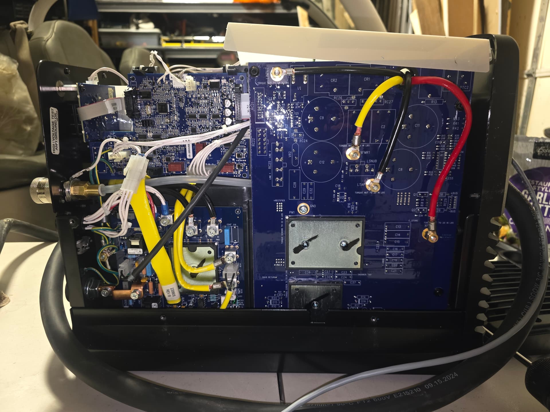
In the image below, this is the black cable routing down to R48 (I did not see this port earlier, which was part of my confusion). This one routes straight through the opening below the CPC port on the back. Also note the white harness connector, which is connected differently than in the video. That one connects to the CPC connection in the back.