Hello,
UPDATED - READ LOWER SECTION
I am assembling an XR and the system is not seeing the Y2 limit switch. After investigating it seems that the issue is in the cable. I can get very brief flashes where it sees the switch if I manipulate the cable in the area of the ferrule where the cables to the individual switches combine. I plan to cut the harness and repair. Or even make a new cable if I need to.
Does anyone have a diagram or schematic for the cable?
UPDATE;
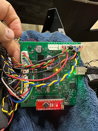
I rang out the cables and chased the issue back to the control board inside the electrical enclosure. I can completely disconnect the cable inside and watch the Y2 indication at the bottom of Fire Control turn on and off by itself randomly . If I touch the board at the connector it toggles quicker. I measured the voltage on the input pins for all 3 limit switches and the X and Y1 it was floating at just under 5v. The voltage at the Y2 pin was about 1 volt. I suspect there is a bad trace or pull-up resister in the Y2 circuit.
I called Langmuir support and got a message that they were not answering phones today due to company training.
I have some work I need to do with this table. Is there a way to operate without the Y2, or without all 3 limit switches?
UPDATE #2 - RESOLVED
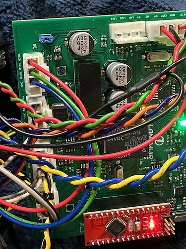
After some inspection I discovered a missing jumper on the control board that appears to only be used for the Y2 limit switch input to bring the proper pull up resistors into the circuit. The pins for this jumper are in the upper left corner of the board. Once I found a jumper and installed it all of my problems were solved. Except now I have to put all the wiring I pulled apart in my troubleshooting process back together.
Thanks.
Kenric

