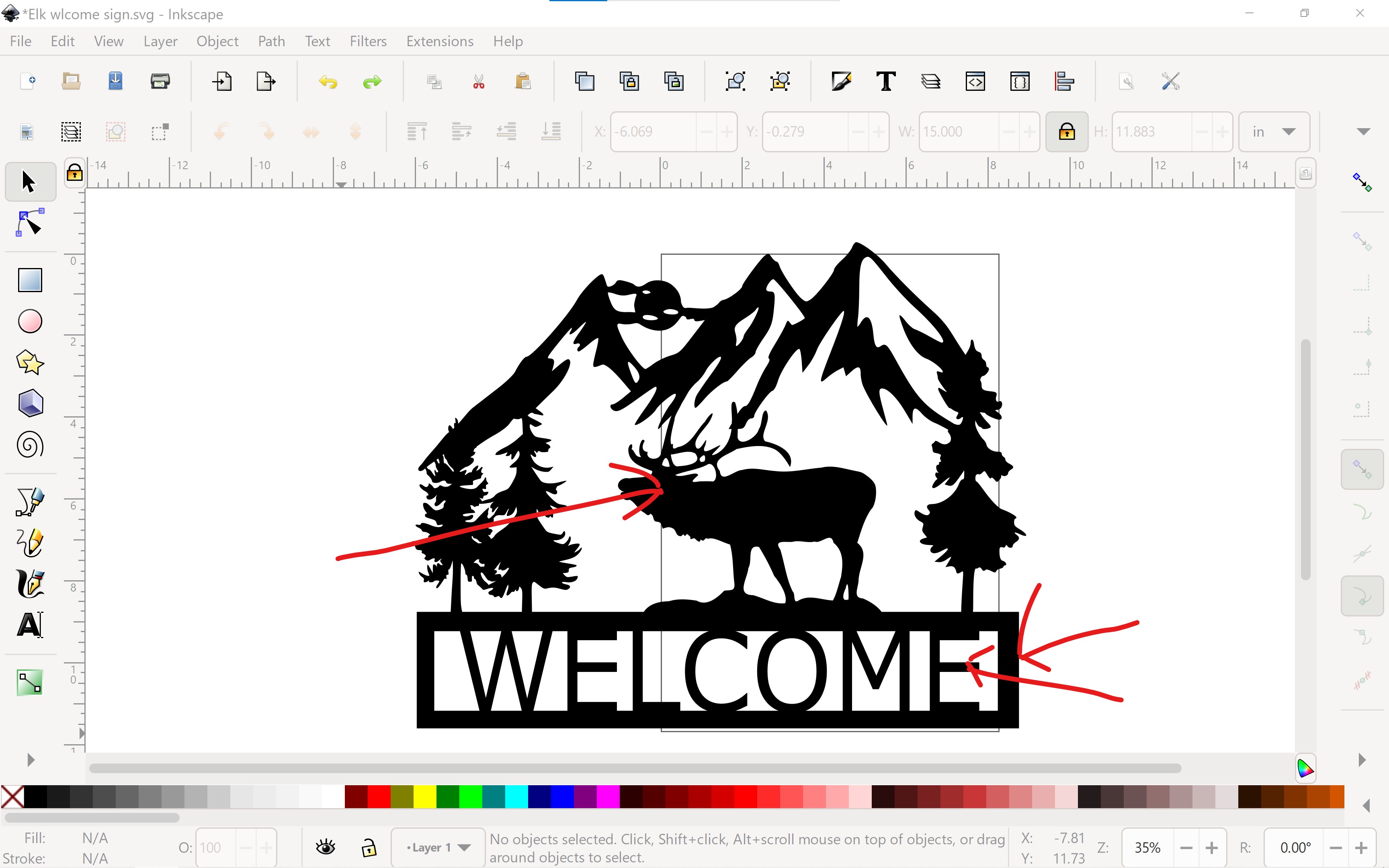
Can anyone tell me how to edit my drawing file in inkscape?
I need to move the lettering, it will not center now that it is a union.
Give him an eye, cant get it to union it just disappears!
I also need to fix the welcome box size, its not the same all the way around.
I would convert it to curves if not already and then break the curves apart. Once you have the curves broken apart you can delete the portions you don’t want. Its a little in-depth for me to be typing up a tutorial on that. I would try looking it up on youtube. deleting curves in inscape.
If you don’t have the experience the easy solution would be to find the dxf file on Etsy. I’ve seen that one quite a bit online you would be able to buy it for under 5 bucks and then you can edit it to your likely really easy.
I’ve been using Inkscape for a while and I have no idea what he’s talking about with breaking curves apart.
If you want to add an eye, you need to “difference” not “union”. Union adds to the design, so it will just become part of the larger piece and fill in. Difference will cut it out of the larger design and leave a hole.
The letters will not move because you “unioned” them and they are part of the whole piece now. You have to go to Path and “break apart” to separate them again. They will all be separate things, so you will have to “group” them to keep the letters together as one object. It will also break apart all of the other separate pieces of the design, so you will need to select them all and “combine” them to put it all back together.
It’s a lot of work to fix something this way, but if you are still editing it, you can just undo the union of the letters and center them with the “align and distribute” tools. If you can’t undo the union, it might be easier to just draw a box over the area with the letters and “difference” it away and start again.
David, thank you so much for the help! Your pointers worked for me. I’m used to photoshops workflow.
I do have a question, if I’m working on a drawing and need to close it till the next day do I save “as” and SVG, or just save and SVG?
Also Can I resume the drawing after I have saved it, will undo still work?
The Photoshop/Gimp workfow is a difficult translation. Photoshop/Gimp is a ‘raster’ (rows and columns of pixels,) as opposed to InkScape’s ‘vector’ model. Vectors are lines (curves,) that outline shapes. Vectors are ‘scale independent’, meaning that there is no resolution penalty for shrinking or enlarging them. When you ‘trace’ a bitmap (raster image,) the result is a vector image (e.g. SVG or possibly DXF.)
The curves have ‘control points’ which you can see by clicking on the arrow with 3 boxes (2nd from top on righthand vert toolbar.) These are typically ‘bezier’ curves. If you want to get comfortable manipulating bezier curves, here’s an online game that will teach you: https://bezier.method.ac/
The lines/curves are also referred to as ‘paths’. Along with shapes like rectangles, circles, etc, they are objects. The Paths menu offers a number of things you can do to and with paths, among them, ‘boolean’ operations. Boolean operations allow you to combine, subtract, break apart, get the difference, etc. of two or more paths.
It is often helpful in InkScape to select something (usually using the arrow at the top of the right hand toolbar,) and remove its ‘Fill’ (double click on fill at lower left to get the dialog box.) If the thing disappears, go to the Stroke menu and give it some color. This lets you see the lines that the CNC will be trying to do something with.
InkScape is incredibly powerful, so to manipulate drawings, it’s worth some investment in tutorials like the ones at Inkscape Tutorials | Inkscape
To add confusion (or capabilities, depending on your perspective,) an SVG file can also contain raster bitmaps along with the vector lines. This is really handy on my laser cutter, where the lines serve as the cutout shape and the bitmap gets engraved by the laser scanning the rows and columns of the bitmap pixels.
For the Crossfire, there is no value at all for having a bitmap in the SVG. If you open or import one, be sure to trace it to convert it into vectors (and then delete the bitmap to reduce confusion.)
One more common frustration involves ‘layers’. If you use layers in Photoshop/Gimp, it’s essentially the same thing. But when imported into Sheetcam or some other tools, you have to select the layer that has the lines you want to cut. InkScape can use a single or multiple layer(s), depending on what you’re trying to do, but it can be challenging when you don’t remember the layer plan and having trouble getting the CAM tool to cooperate.
If you’re going to be using Inkscape for most of your designs, Sheetcam will probably be a better option for your CAM. You can create a cut file directly from the SVG in Sheetcam.
I import my finished SVG into fusion sketch. Finish the sketch then extrude it. If SVG has single line cuts or open loops I make the sketch visible. Then go to manufacture. Create tool paths for open loops or single line cuts by selecting each line. Then create tool path for all closed loops by selecting extruded body.
Hey David, I had been doing all my work in fusion but the artsy stuff is hard to do in it. Now trying to wrap my head around another workflow in Inkscape and combining it with fusion:exploding_head: I’ll get it but will take me some time!
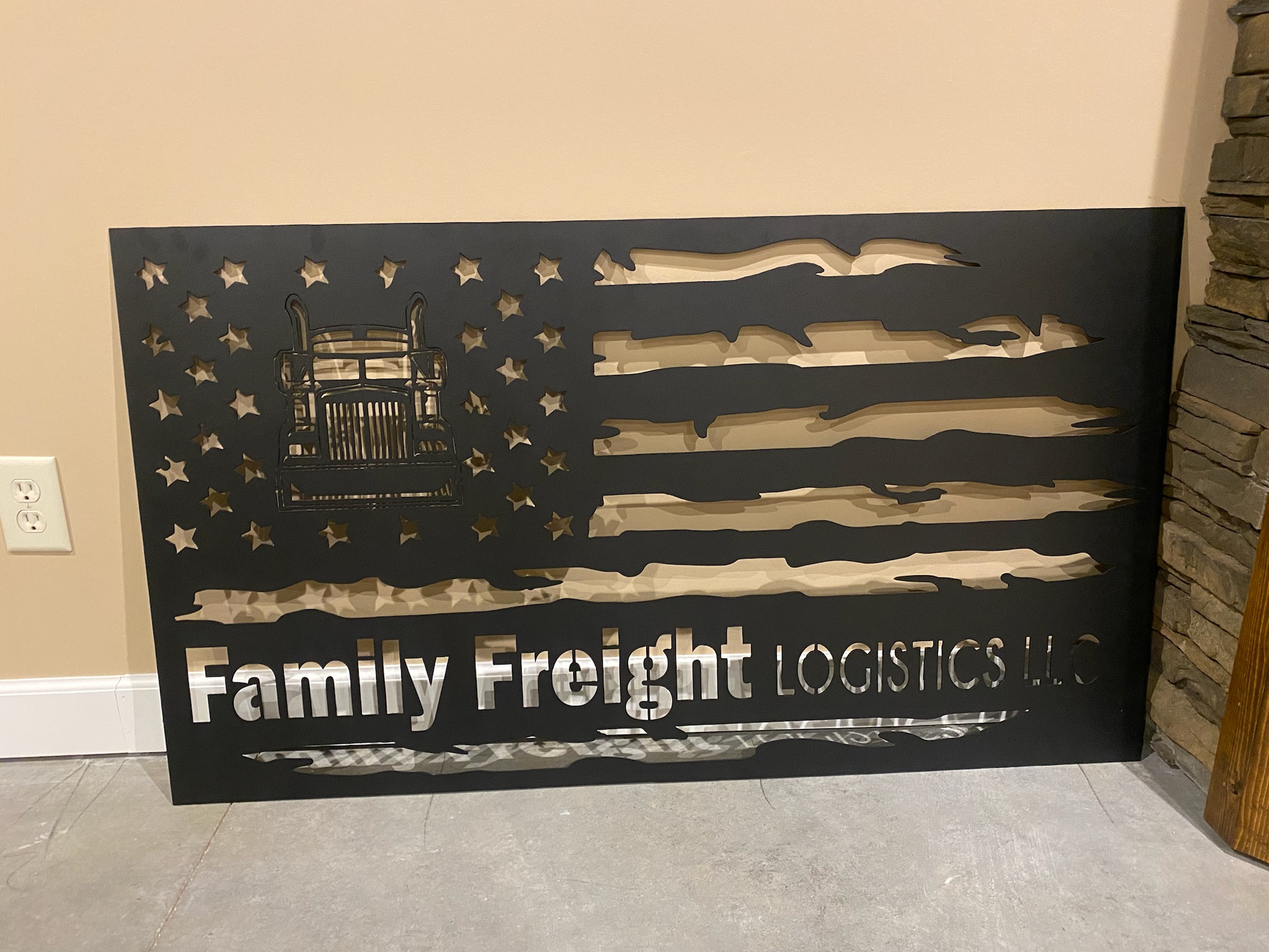
This sign is awesome! You did a great job! Thanks for the workflow from Inkscape to fusion I will try it and see how I do🍺!
I have a question about Inkscape fill and stroke! Do they make a difference in the finished cut size? Should the stroke be pencil thin to make the size accurate?
I haven’t found that fill or stroke thickness affects anything in fusion. I set my stroke thin in inkscape so I can match the shapes I’m tracing better. But to be honest I never really looked at size of an object in inkscape. I’ve always had to scale my svgs up to a cuttable size when I insert into fusion .
Technically the stroke size does have an impact on the size of objects. For art signs and such it’s not likely to be an issue. But the default for Inkscape is to include the thickness of the line in the object’s size. So if you’re really looking for precision you should change the default. That will also let you define the line equal to your kerf and you can see how the actual cut will affect right curves and such.
To change the default, go to Preferences → Tools and set “Bounding box to use” to “Geometric bounding box” instead of “Visual bounding box”.
Only if you want to see how cuts will interact with each other. You can draw things where the kerf will be wider than the space between nearby lines (especially with intricate artwork). Having the line defined as the kerf width (for ones that will be no-offset cuts) or twice the kerf (for cuts you’ll make with an inside or outside offset) will show where the material will actually have the cutouts. That’s what will show you where tight angles and other fine features may end up being burned out by another cut.
Regardless of the defined stroke width, the CAM path calculations are made using the center of the stroke. So if you’re doing an offset path, it will back the torch away from the center of the stroke by 1/2 the width of the kerf. That should let the actual material cut to just kiss the line. For a no-offset cut, it lays the torch center right on top of the center of the stroke and you end up with a cut where 1/2 the kerf width is on either side of the line and your part size is reduced from the design as a result.
I do my designs using a hairline stroke and the Geometric Bounding Box setting so the dimensions in the drawings are true. Then if I’m doing tight artwork, I’ll bump the stroke width to the kerf or double-kerf just to see if I’m going to have any issues with overlapping cut channels (CTRL-A to select all and then set the stroke thickness to the kerf…CTRL-Z to undo before I close the project so it’s back to normal).
Good Morning Jim, I not quite understanding the part about “no offset and inside or outside offset”. I’m assuming no offset means “cuts on the line”
and inside or outside cuts "inside or outside the line correct?
Do you use fusion or sheetcam?


 good to know!