Been trying to figure out the tool offset to get my holes on size.
I have a CNC mill and use another CAM program to make that run, but haven’t had enough time to really get into Fusion to find the right Way to offset the plasma to get it cutting on size.
What I have is a Miller 625 and the kerf is .060 thou and I have tried to set the tool to that size and I have set compensation to the left in the tool path to the inside of the hole and what I am getting is a hole that is about .070 thou larger.
I have played around with changing the different diameters in the tool definition and I have found by making the tool bigger the hole gets bigger which is reversed from normal CNC mill programming.
Please if you have A standard way of setting up the tool I’d appreciate any help.
Sounds like you are cutting the outside of the circle instead of the inside. Simulate the tool path and see where the path is showing the cut. If it is cutting on the wrong size then click the red arrow when selecting the toolpath for the parameters of the cut. This will change what side the toolpath cuts on.
1 Like
No it’s on the right side, the lead in and out are as it should be.
My issue is tool definition and the right number that needs to be put in to the kerf box. My kerf is .060 on the torch so should it be 0.0 or ???
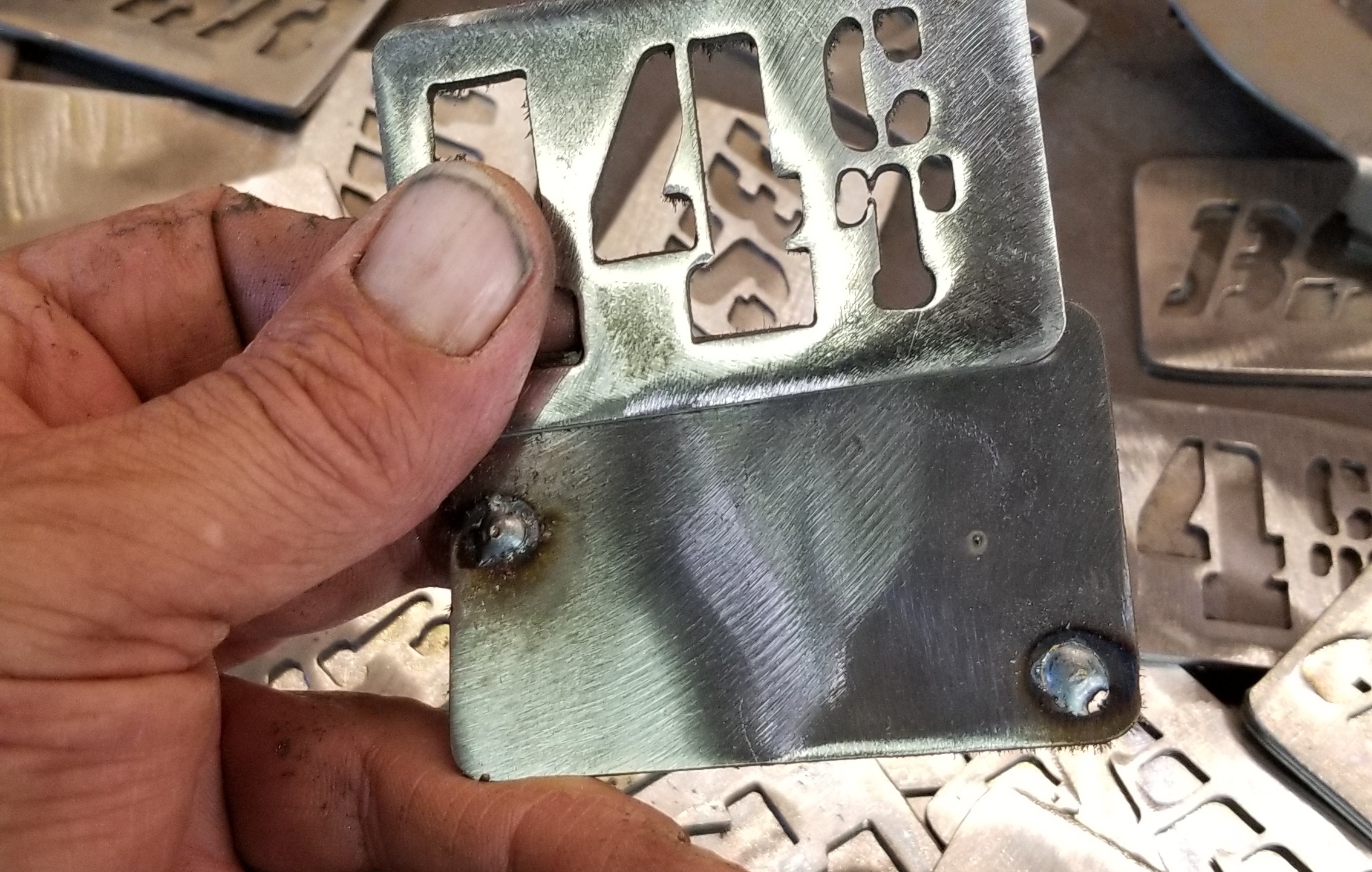
With my 625 ex cutting 14 ga at 150 Imp with the 30 amp tip I am cutting a .030- .035 kerf so I made a new tool in fusion and stopped using the
.065 tool i originally made and it cuts circles and shapes exactly to size so far.
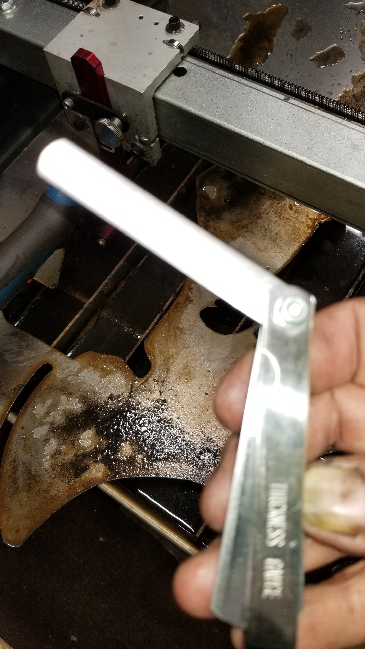
But since we have to use drag shields I use a feeler gauge to set the torch height @
.035 as Miller recommends.
But, I am new to this so still exsparmenting. I dont know if this helps but it is what I have been working on.
These parts came out exactly 1 7/8" and the small letters have a great clean cut.
You need to do some tests to verify what your kerf really is in each material & tip combination. The .06 in the videos is an average of plasma torches over a variety of materials. I’ve also seen .055 recommended by other mfgs as a starting point.
But to be precise you should create a small design with a couple of different sizes circles, a couple of squares & rectangles and a couple of straight line cuts.
Cut a circle offset to the outside, one offset to the inside, same for the squares and no offset for the lines. Then measure your holes and your cutouts to see what the difference you have between your drawn measurements and reality. Use that kerf value for that tip & material combo (worth writing it on the sample blanks with sharpie so you can compare cuts as well as your consumables age).
Here’s a user friendly way of changing hole(s) sizes or outside cuts also.
I uploaded a couple files, you have to rename the .dxf part to .tap since
we can’t upload .tap files.
They are setup to run a 2 x 3 rectangle w/2 .750 holes in it.
Run program -01 and measure it you’ll find the holes will be
large and the out will be small, then run -02 and check it I
used your .060 kerf adjustment on that one you’ll see that
the holes are smaller and the outside is larger, both programs
are the same except the kerf adjustment.
One thing you’ll see when you do regen in Mach3 you now see
a white line around the inside of the circles and around the outside
showing where center of the torch will cut.
It’ll allow a change to just one hole if need be or if just the
outside needs a change.
z-test-01.dxf (437 Bytes) z-test-02.dxf (434 Bytes)
2 Likes