I’m not sure what’s going on here but please watch the video and let me know if you can help. I’m trying to set a tool path for letters. Had no problem with the other ones but for whatever reason, it will not create the tool path for this letter E. I have two letter E’s on the same line, but it will not create this one, CRAZY! Please checkout this video, let me know if you can help.
Is the error you’re getting the ever so popular “some passes were -------> due to linking constraints”?
Hi,
I just watched the recording with no sound, an it’s definitely a linking constraint issue. I’ve had the same problem with holes that were of equal size, heck some larger holes didn’t want to work.
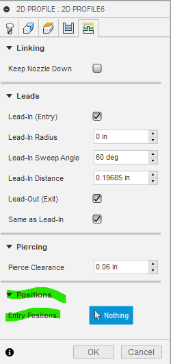
It looks like it’s a combo of your lead-in radius and distance on the last tab. A lead in radius of .04 is fine for most small holes, but the disance of ~.2 is pretty big. For small holes, I generally have my lead in radius and distance set around .03, but I also go with a .6MM tip when I have to do something detailed.
How large are those letters?
1 Like
Yes, it is. Fusion 360 has a lot of problems.
The letters are 1.3 inches high
It’s usable, and for free I can’t complain.
I’m tempted to check out Sheetcam, however I’m not sure if it’s much better. For me the biggest issue I have is with lead-ins in general, and how the software just doesn’t appear to be intuitive.
For example it would be GREAT if a program just treated interior pieces with lead-ins that match the size of the hole, or at least let you set where you want the lead-in to occur. (unless you can do this and I’m blind).
Holy crap I thought that was for a single lead-in… Interesting, that’s sort of a game-changer then.
Also I did notice the pierce clearance wasn’t changed which isnt an issue but if you dont have enough room inside your cuts it could give you that error as well. Also not sure what you set the kerf width to for your tool setup, but it will not allow it to make a tool path if the tool overlapses exsesively from what ive seen. Just some thoughts.
1 Like
Thank you for your reply. The kerf is set at .055 per langmuir systems video. I have to assume that’s correct. What would you suggest the pierce clearance to be
I’ve tried that to to no avail… thanks
It’s funny… I changed the Lead-in radius to 0 and it fixed all the problem (probably created a whole bunch more and don’t know it yet)
Any thoughts?
I have changed my lead-in radii to extremely low as well on very small holes, and didn’t notice any issues.
The only way I guess would be to test.
1 Like
Good directions given so far.
I can’t stress enough that test cuts in the material your using is an absolute must if you want any quality. In your pieces. It also help tremendously with Kerf width calculation!!!
Knowing this Kerf with allows you to program your cuts and set lead in, outs, etc to help avoid these FUSION linking errors.
Once I know my Kerf I always draw a filled circle and run it over my text and designs to rule out fit and cutting errors on the size and width of my sketched items.
Plus you can now also set up your cutter in Fusion with the correct Kerf and not an estimated one.
1 Like
I’d also suggest setting up multiple tool definitions based on tip & material. Your kerf will be different for each combination. Maybe not a big deal for art pieces, but if you’re cutting parts you want to be sized precisely then the tool definition needs to reflect the reality of what the kerf will be on that material or the computer’s offset calculations really aren’t worth much.