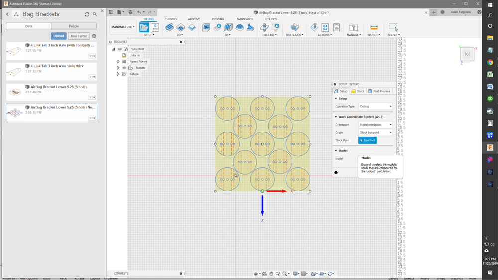
Getting very frustrated in trying to get a grip on how this all works in Fusion 360. I have created the pieces I want to cut out and when designing the parts to cut out, I started a new sketch and selected the lower right square/orientation. That is the correct X/Y axis to start with, right? I Rectangular Patterned the sketches. Everything is looking great, I think. However, when I go to create a setup I am not sure that the right axis are picked. When I start a new setup, I am shown the X and Z axis arrows, not the X and Y axis arrows like in the Langmuir video. What do I need to do to fix this? Please help
You are picking the “top” axis, for our 2d work always pick the “front” axis. Use the box in the top, right hand corner to set it up. The axis on your drawing there can be changed but without my laptop to look at I forget how to do it.
Thanks! Once you get back to your laptop, I would love to know how to change the axis in my drawing.
Going from memory, when your in design, click on the grey box on the very top right hand side of your screen, dropdown box may have a orientation option.
Could be wrong.
You could always ask @jamesdhatch, he straightens out everything I mess up.
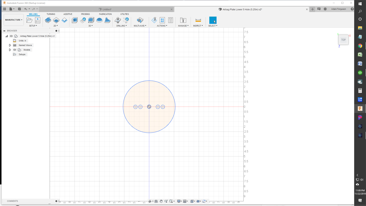
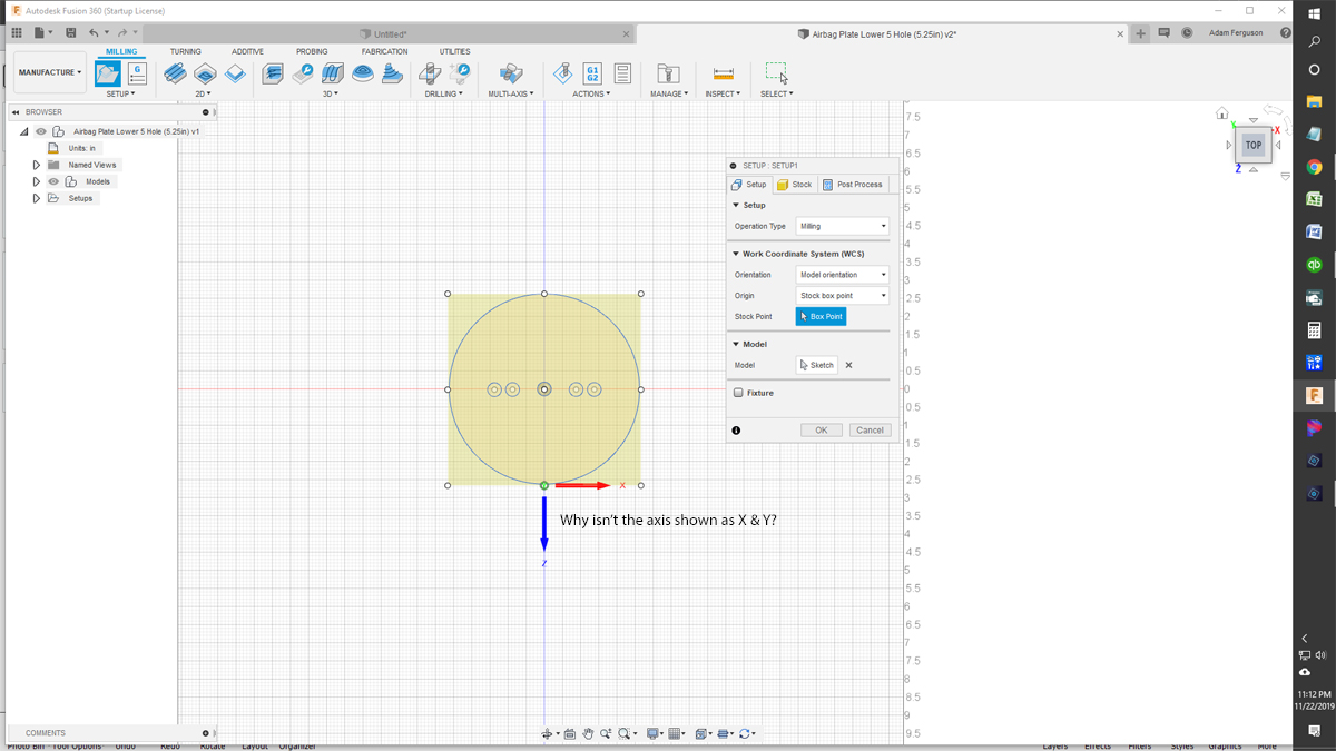
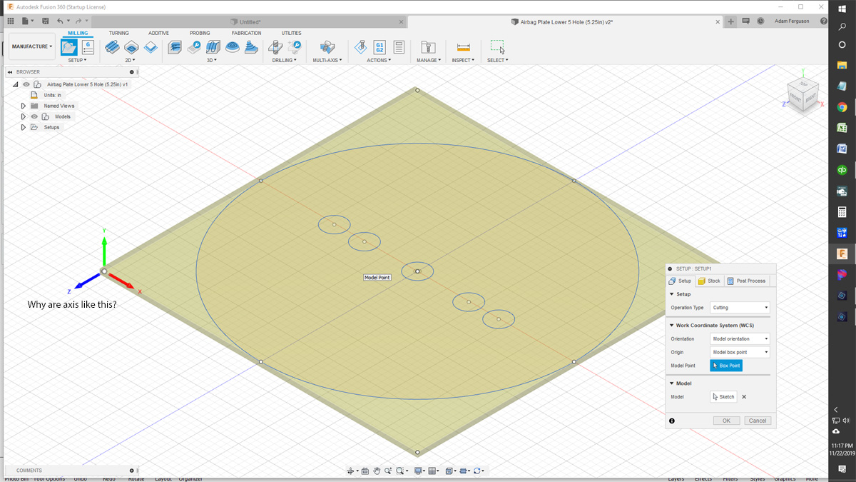
I have started over and started over and started over. I need help. Trying my best to do as videos instructed. I created a new design of my circle plate. Finally got to trying to do a setup again and my brain has almost exploded. Trust me it wouldn’t be a big explosion! LOL. Anyway, upon creating a new setup in the “Manufacturing” section (CAM), I go through the steps and click “New Setup.” I see the box appear around my design as it should, but I can’t help but notice that I am not shown an X and Y axis arrow like in the Langmuir video. Instead I see X and Z axis with the Y axis pointing up out of the screen. Please see screen shots below. I absolutely can not figure out what I am doing wrong. Can anyone please help me with this?
Adam,
I have better luck pointing towards a video or webpage than trying to explain sometimes… It’s in my head but, sometimes have a harder time putting it into words. I guess I’m a more visual person. Anyways take a little time with a cup of coffee and check out these links. I’m fairly sure they will help you out… LOTS of information here…
Good luck and please let us know if you got it worked out… If not, please let us know that as well and perhaps someone has a better way of explaining it…
1 Like
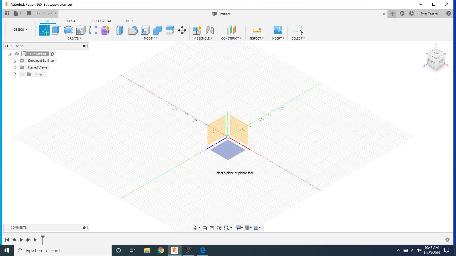
From what I’m seeing, yes you could change the orientation to fix it. But what I think the main problem is from the start you probably started your design on the wrong plane.
2 Likes
This is probably how you started your drawing
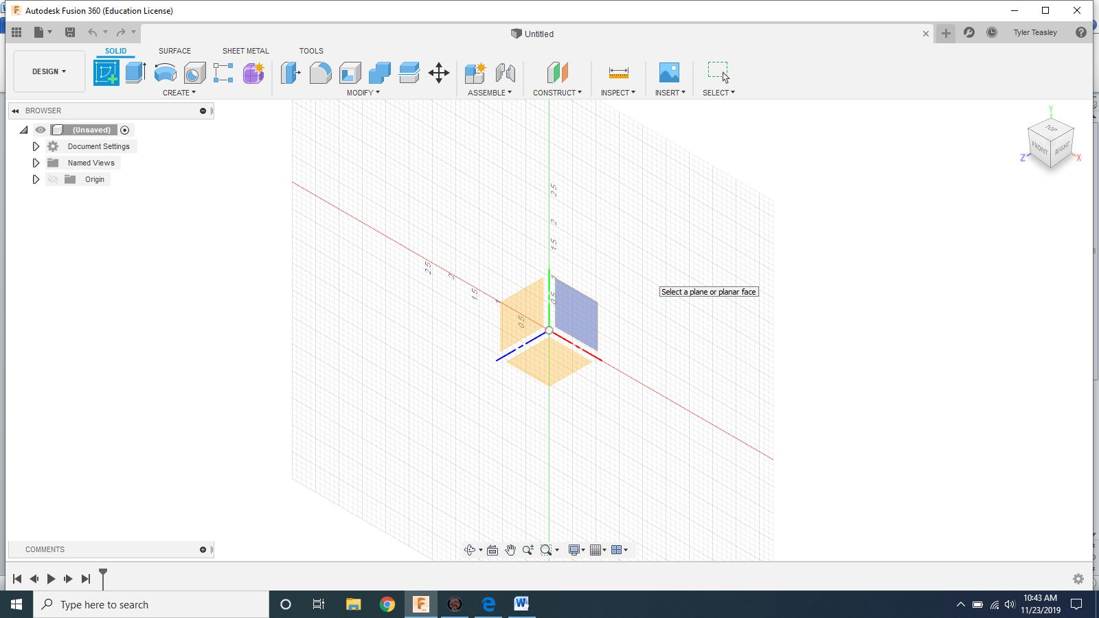
This is the plane you should start your design/ drawing
2 Likes
Yeah? That thought crossed my mind too. When first creating my sketch, I thought i was supposed to click the bottom plane. Is that correct? Seems like that would be the X Z plane, not the X Y.
In the Langmuir vid, he says to click the bottom right plane, but then when he does the Setup vid, he says top right.
The way I do it is click the (TOP) on the upper right orientation box. Then click the blue box that is in the middle portion of the screen. then load the dxf/svg that im wanting. That puts the bottom left corner of the project in the right place for what I zero my table to. As far as selecting new set up I always pick the lower left corner. Others may do it differently but thats a good way to learn the basics.
1 Like
The setup might look/ be a little different on different computers, just look at your cross hairs and make sure you pick the plane that looks like my second screen shoot, it might be rotated in a different direction
That’s spot on. You want the positive X, Y axis at the zero Z intersection.
The others are negative directions of X, Y or Z.
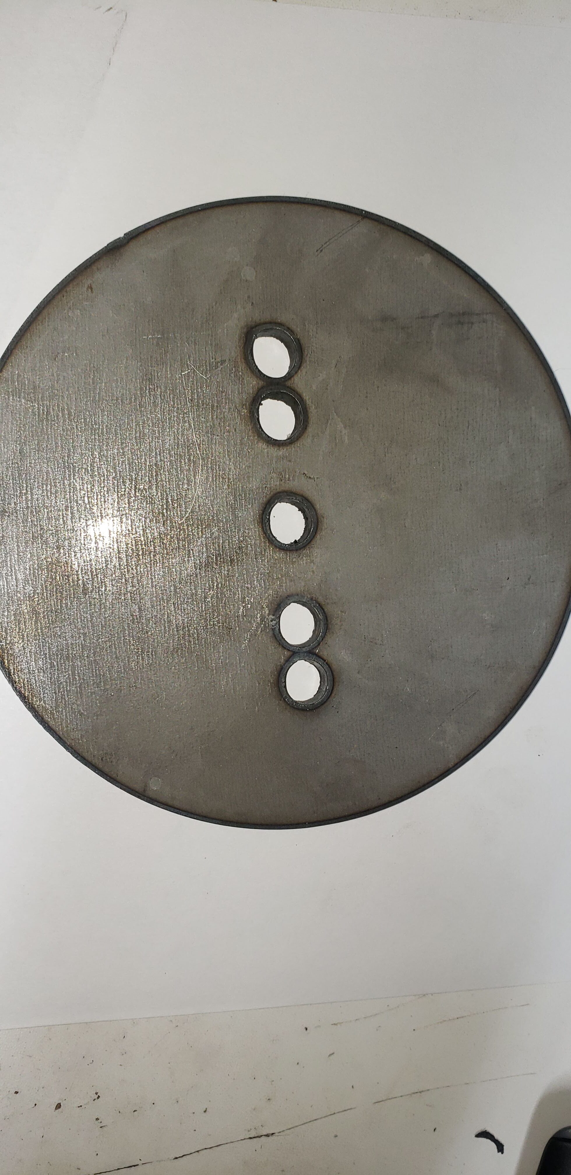
You guys were right! I had my initial drawing/sketch on the wrong plane. I decided to start fresh and BEFORE creating a new sketch, I clicked on “TOP” in the view box in upper right corner. THEN, I selected the plane on upper right of axis intersection. I created my new sketch and followed all of the procedures to design my circular plate. Upon creating a new setup in CAM/Manufacturing, the X Y Axis arrows were shown as they should and the Z axis was pointing “out of screen.” I was able to complete the toolpath generation and post processing. I emailed the .tap file to my dedicated laptop at my Crossfire and have successfully cut out my plate! I have a few adjustments to make on my design, but I’ll save that for tomorrow. Thank you ALL for your awesome help! I’ll talk to you soon!
(Cut Out! 3/16 cold rolled steel, Razorweld 45 @30 amps, 30 inch per min.)
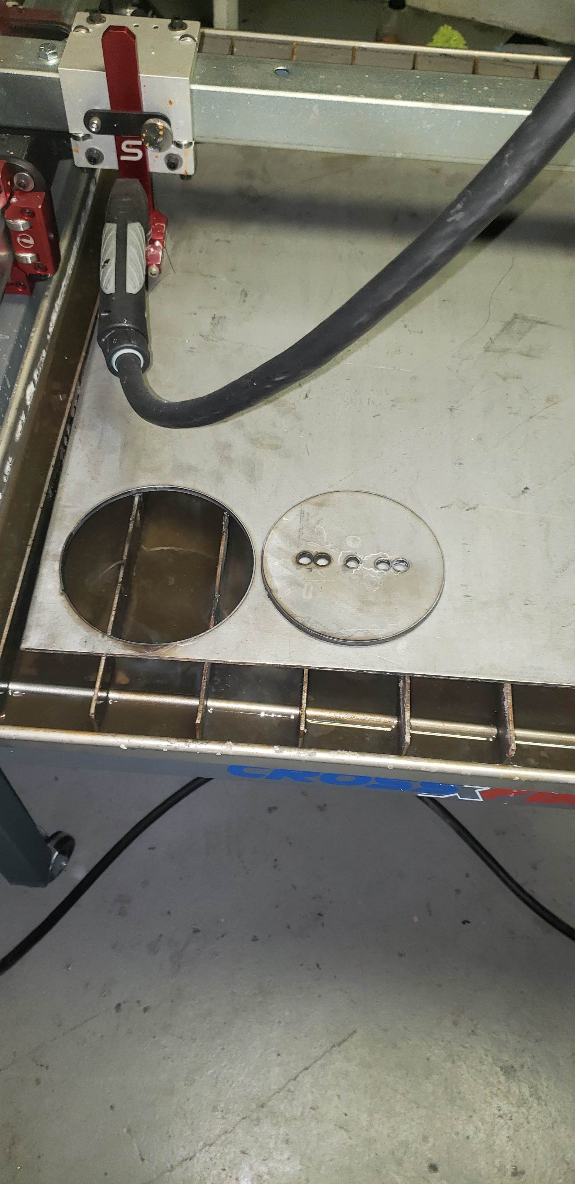
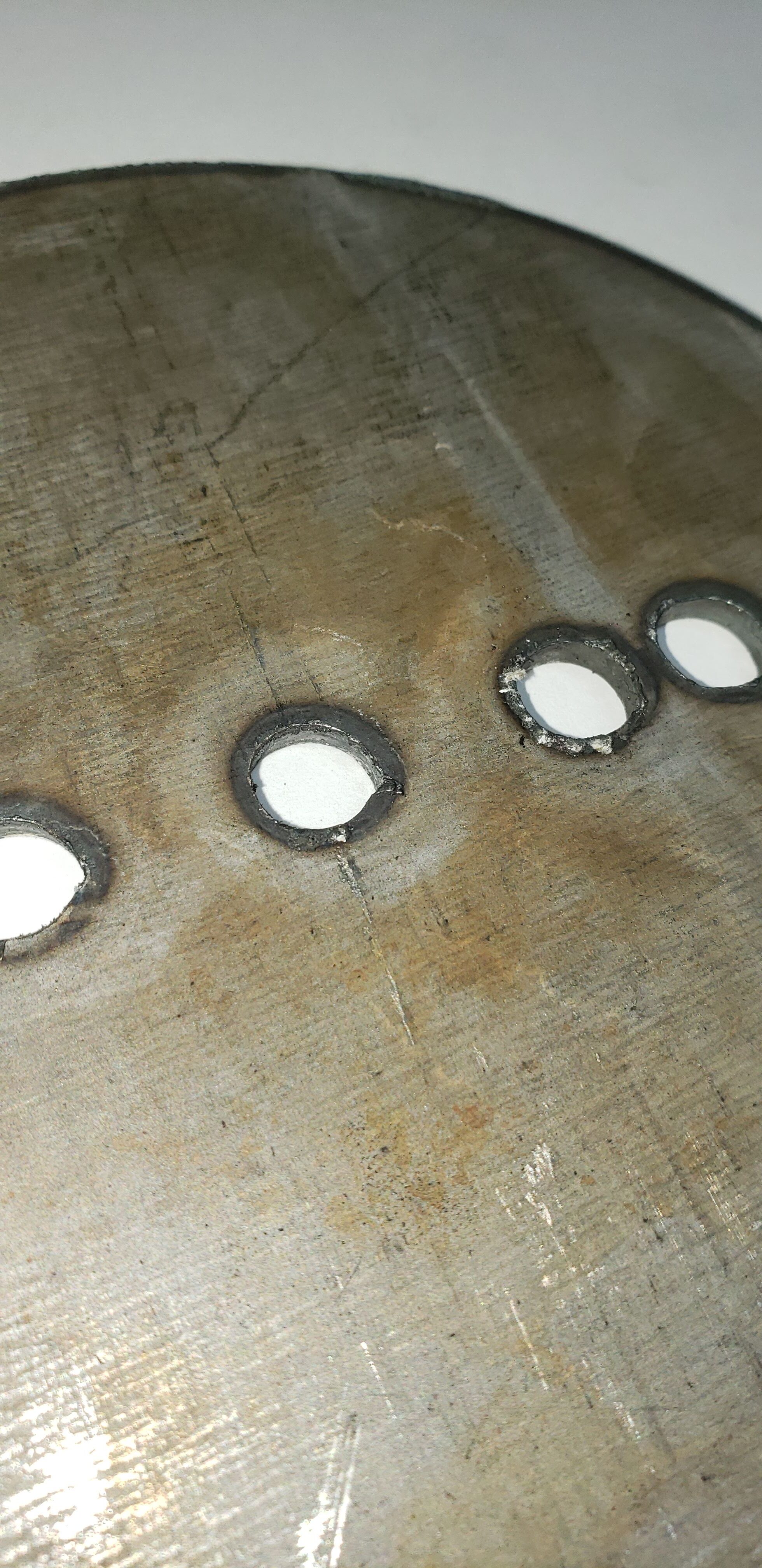
(Holes aren’t as perfect as I was hoping for and don’t know why)
(Ugly pierce mark)
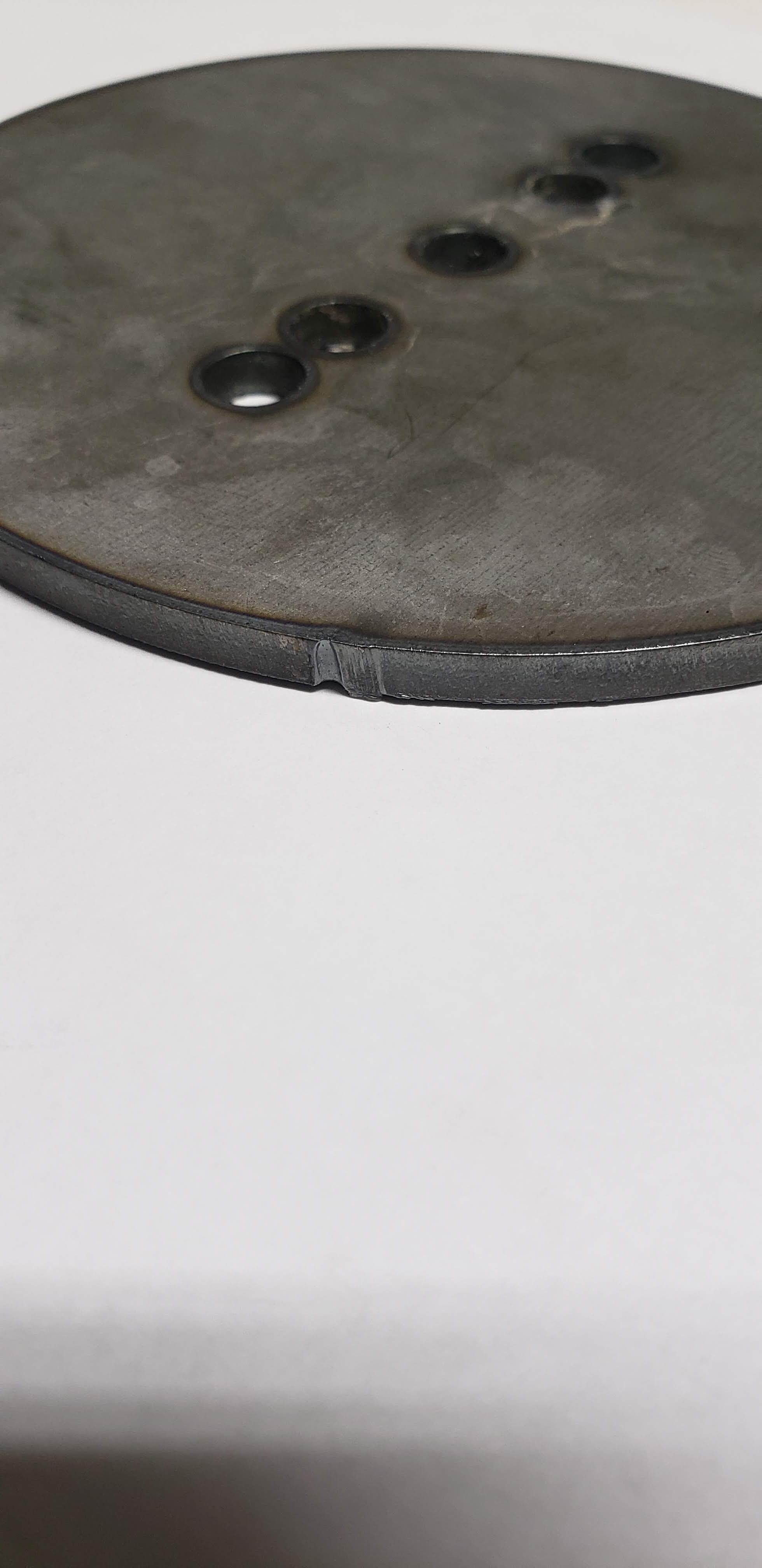
(minimal Dross on back side! I could easily pluck it off with finger nail)
Glad your up and going. most here has been where your at now. You just have to learn it all. Once you get onto it ,its a blast making things. Make sure you keep them lead screws tight. That will cause lots of problems. I used blue loctite on mine .
Alright, alright. Alright
Jimt is exactly correct in his post, it looks like one of your lead screws is slipping and causing out of shape holes. Loosen your allen screws on you drive motors, turn them in until they just touch the the lead screws, turn the motor slowly and find the groove with the screw tip, tighten the living heck out of them, beyond what you think they will take. Try to clean or degrease them and the threads on the collar before applying a little loc tight. That is a nice piece of 3/16" plate to be practicing on. Some cheap 18 ga is less painful to experiment and practice on.
Glade to see you make some progress, it is a lot to learn but it gets fun real fast from here.
Hello yourcustomcar,
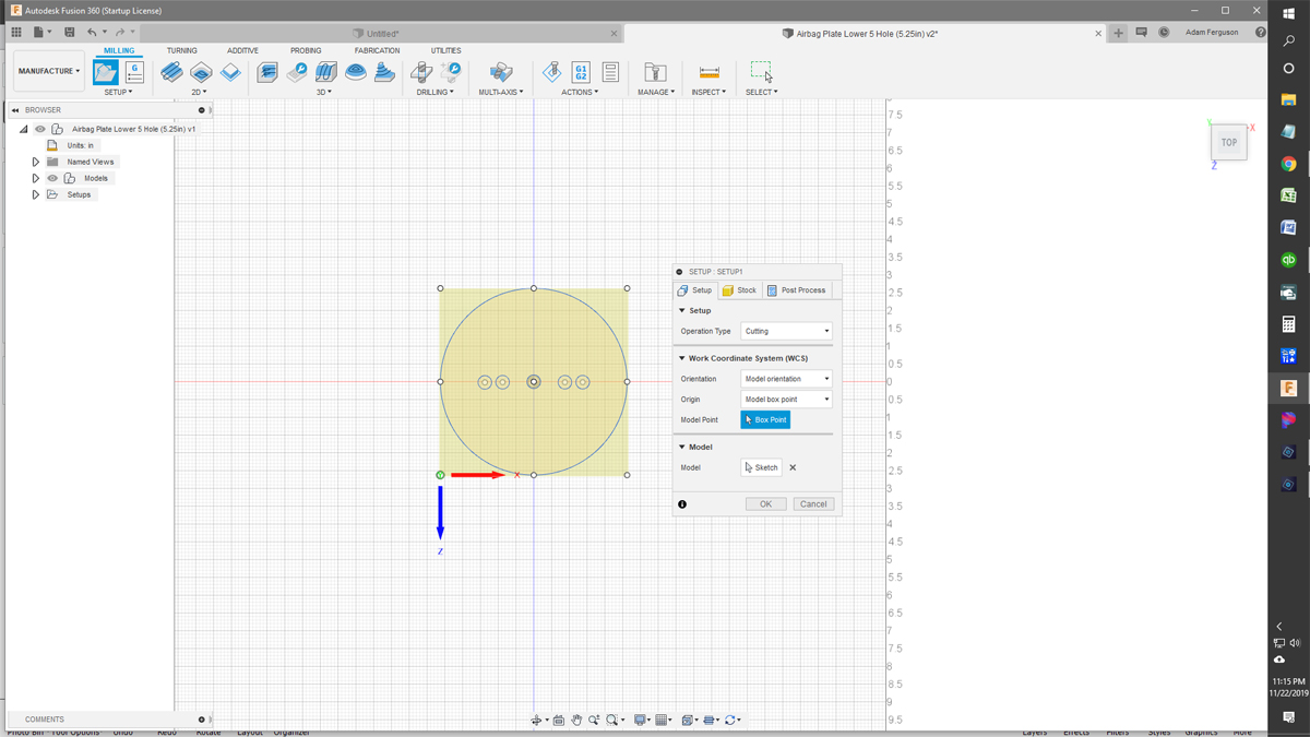
I wanted to point one thing out for you regarding your setup question. Regardless of how you initially create your model you can control the direction and orientation for you Axis in the setup menu. You can pick which way you want Z and X regardless of how you started your model. Hope this helps.
In my opinion, your circles are distorted from either the lead screws coming loose (VERY common problem) or you have the IPM still set at full speed. (On small circles you need to cut it down a lot, I usually go about 55-60% less then the rest)!
To the OP, you discovered the easiest way to get your CAM setup orientation right is to build it right to begin with, but you can set your origin point in CAM regardless of what orientation your part was in when you built it. If the axis arrows are not in the correct orientation, you can simply click the arrows to flip their direction. That, and the options for selecting the X and Y axes will fix it every time.
1 Like
Thanks Ryan,
Orienting the design the right way from the beginning is definitely the best way to go. Although after much tinkering and coffee I was able to change the x, y axis after discovering that that was possible.