Anyone want to take a look at this and tell me what I am missing
Mounting plate x 3 v1.f3d (91.9 KB)
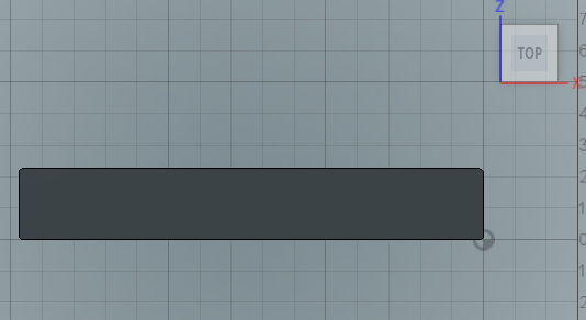
The body appears to be in the XZ plane:
But I cannot find the sketch.
Manufacturing seems to be happy with how it is set up. Was there more than just the outside cut?
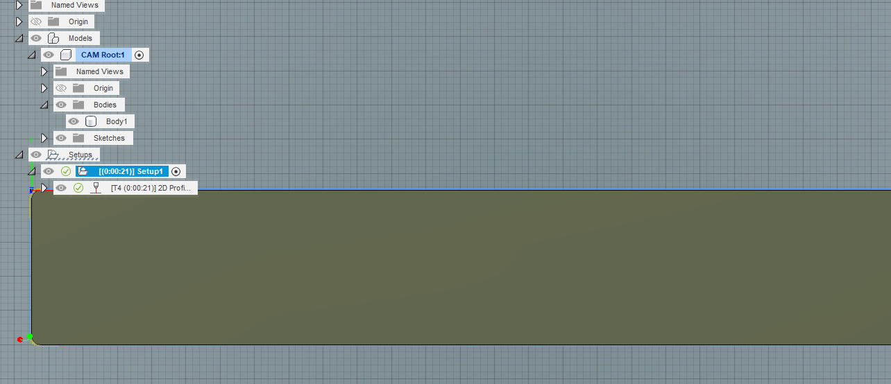
Yep. It appears the sketch is gone:
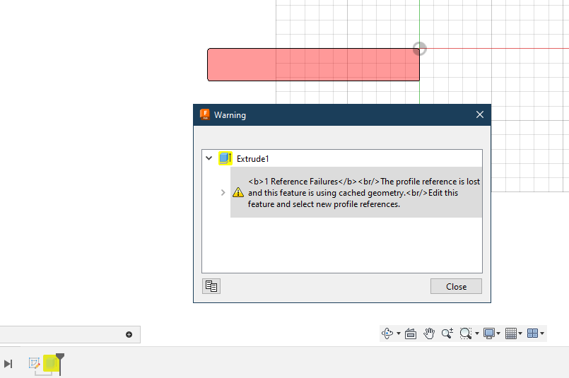
And, when I attempt to edit the reference, it will not allow it. Perhaps because the sketch is empty.
I am only showing a lead-in
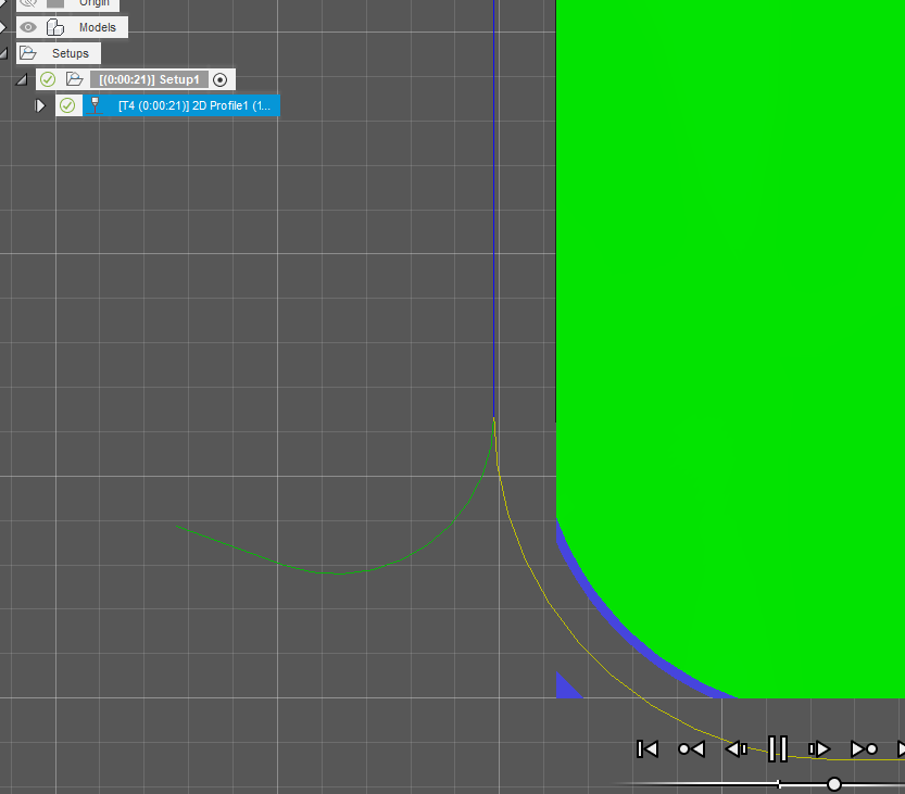
If I turn on the lead out, I definitely get both:
Ok so I drew it over again
Mounting plate x 3 v1.f3d (87.4 KB)
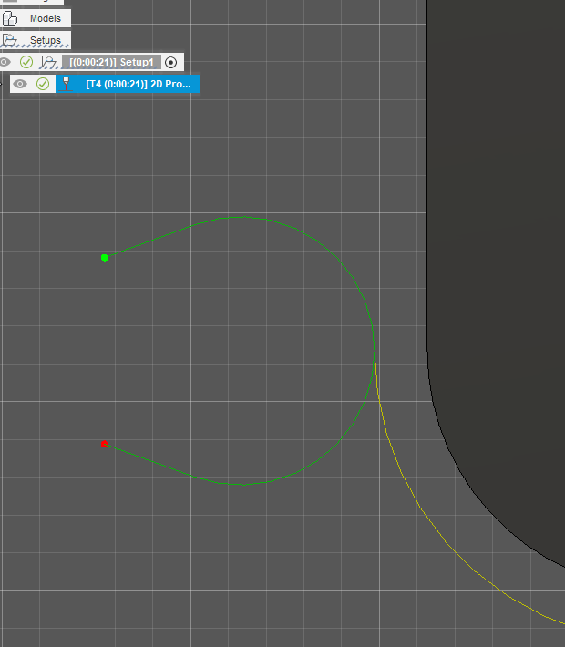
Here is how it looks for me.
Maybe that’s not a lead out as its yellow. I don’t remember ever seeing that before. I just got a update maybe they made another change.
The lead out should end with a green dot (kind of counter intuitive). I guess red indicates the torch starts and green indicates “all clear.”
Since you are not showing a green away from the cut, I would say you are safe. If you look at that first image I grabbed, the green dot is on the cut line.

So I think it is doing what you want.
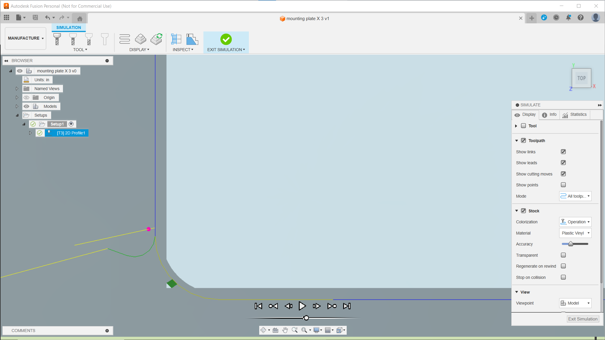
Its weird that pink dot will go all the way to the end of that yellow line. Who knows after all it is fusion!
Maybe its just me.
That is weird and I was going to comment on it appearing pink. Mine is definitely a strong red color. ![]()