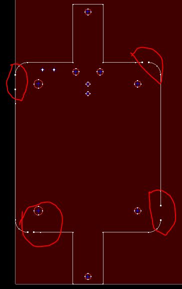
I’ve generated a DXF for a sheet metal part from Solid Edge and when I import into SheetCam it has four fairly large gaps in the perimeter. If I load the same DXF into: Inkscape, SketchUp, CamBam, there are no gaps and the perimeter is continuous. I’ve posted this on the SheetCam forum but it’s taking a while to get moderated… so I thought I’d ask here and see if there is any guidance on fixing this. The DXF is attached below.
Looking at the SheetCam image, it appears as if there is a gap when a line segment (actually a spline) begins at a straight line and terminates at an arc, and there is NO gap when the line segment begins at an Arc and terminates at a straight line segment. Furthermore, it also seems as if the gap size is proportional the length of the segment leading up to it like there is some gross scaling error. Given three other programs consumes this without any problem, ISTM the issue is with SheetCam…
Seems like I saw a post a while back that had something to do with layers not showing up in sheetcam. Check under View -> Layers tool and see if perhaps there’s another layer. There’s also a check box when importing - something about layers / colors…
I always have the layers window open and it doesn’t show any additional layers. Also, I’ve since imported into FreeCad and QCad and both of them show a closed perimeter. CamBam only had the two layers in its data. I’ll fish around and see if there is any ‘color’ quirkiness.
I reloaded the DXF into CamBam and selected all the objects in the outer perimeter, did a ‘join’ which created a single polyline, exported to a new DXF and that loaded into SheetCam without a problem. There’s something quirky in SheetCam. I won’t say it’s a bug (yet), but it sure doesn’t like this file!
Shall I post this as a workaround (using CamBam to fix it) on the SheetCam forum?
It may be the type of line defined to tie those boxes together. Try manually extending them or adding line segments.
It’s not uncommon for design programs to display objects differently than they are rendered in the file - the typical one is dashed lines. They look like separate lines but they’re actually two points with a display filter applied that shows it as dashed.
I wouldn’t be surprised if that’s what’s happening here.
If you saved it as an SVG and brought it into Sheetcam does it do the same thing? I try not to use DXF much as the different export/import routines the different products use to create or consume the DXF format are all over the place in terms of results.
Well, here’s how the junction was ‘designed’ in the first place. I drew a rectangle and then applied a fillet to each corner. The piece was originally extruded to a 3D part (where it’s part of an assembly) but then I imported it into the Sheet Metal application and flattened it, outputting a DXF in the process.
Solid Edge would have never extruded it in the first place if it had been open. Unfortunately Solid Edge doesn’t offer an SVG output choice. All kinds of other 3D Cad formats or, under image types, only true image formats (JPG, PNG, etc)
I’ve loaded the DXF into both Inkscape and CamBam, both of which I can zoom into the ‘offending’ nodes, and there is no discontinuity (other than there are two intersecting segments at overlapping nodes. The more I think about this and the oddity that there are two sets of gaps, both of which appear to be proportional to the segment length makes me think SheetCam’s SW isn’t handling this type of intersection with the same scaling as everything else.
No response from Les, unfortunately…
Thanks for your suggestions and I do have the workaround, so I’m not stuck - just bothered that all isn’t right with the world
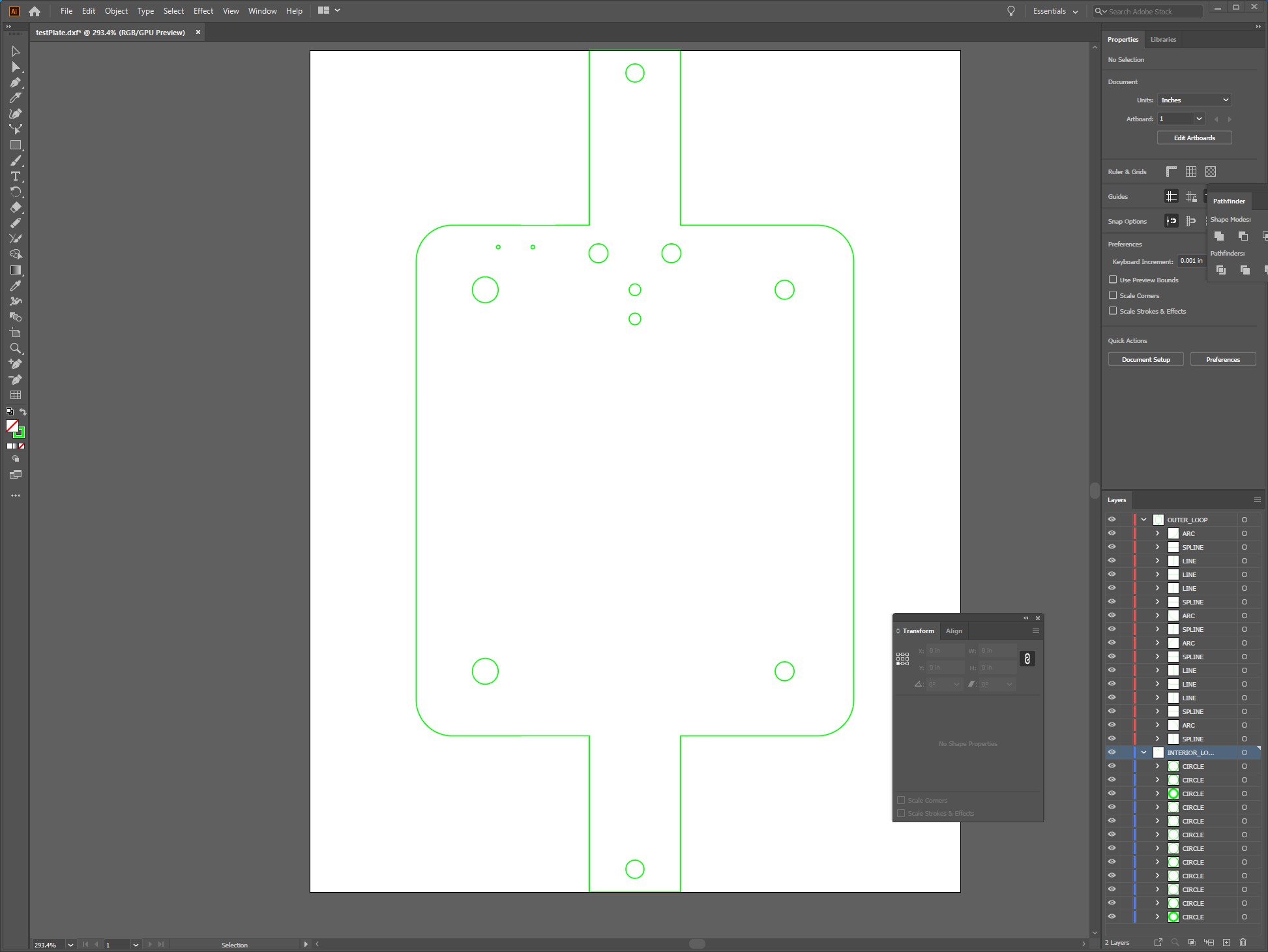
Just another data point for you from another vector program - I imported into Adobe Illustrator. Seems fine - no breaks. It recognized 2 layers - an inside and outside.
Still waiting for a response from SheetCam forum although it is academic as the workaround is solid and not especially difficult (as Workarounds go). Probably could do something similar in Inkscape, but CamBam is actually much easier than Inkscape in this case.
I’ll bet that did it. The fillet is a different drawing object than the box - you’re essentially doing a Boolean against the two objects (the box & the arc) with the original corner being discarded. DXF doesn’t do arcs natively (they’re splined objects) so I bet there’s something in the file that’s mucking it up in Sheetcam. It could be old definition files or conversion routines in Sheetcam or a known defect in the way DXF describes the artifact that everyone else has coded around.
I’ll be interested in seeing what you get back on this one.
As a follow up, I did get a response from Les at SheetCam and he suggested exporting with DXF version 12 selected. Fortunately that was an option on the export and that did ‘fix’ the problem. He admitted that the DXF file was technically correct, but it was messing up his spline code.
I wonder if this will be a problem later on, but, for now, I’m not anticipating anything that I’d expect problems.
Thanks James and James…
As a followup to my followup, I ended up merging the plate that was failing in original post, with another plate for the same project. Since I wanted the G-Code to keep related layers in the same operations (holes first, cutouts next, and finally outlines), I decided merging DXFs in Inkscape was the best approach.
Well! Using DXF Version 12 was a REALLLLLLY BAD idea! Scaling was all F’’’’’‘d up. I switched back to V14, imported both DXFs into Inkscape, oriented them nicely and output a single SVG. SheetCam was more than happy to accept that and, voila’! A single SheetCam job with two parts, three operations (four if you count the embedded M6 to halt processing while I changed nozzles), and twice nicely cut pieces with no gaps and fine, except where a bit of tweaking on the nozzle height would have improved the profile.
There are probably two morals here, one, if you need to adjust your settings to a back level version, there’s probably a better way to do it.
@jamesdhatch, @James,
Well, I knew it couldn’t have been THAT easy!
I discovered today that apparently SheetCam is still working with the 90 DPI value from the earlier version of InkScape. Importing the design as SVG I had to scale the drawing by 0.9375 (90/96) to get the right dimensions in SheetCam.
Oh well, as long as I know this…
Seems odd that I’m only running into this now… Maybe my previously imported SVGs were created with the earlier InkScape. Maybe I should check my last design output. UPDATE: I just checked the previous design and it was scaled correctly, however, the difference was that that design was using Metric units… Very perplexing…
Interesting. I’ll have to look at my stuff next time. I use CorelDraw to create the 2D stuff if I’m doing my own stuff. I use Inkscape to teach class because it’s free & I know everyone can download it and will have it. For 3D or sheetmetal projects I use Fusion - the sheetmetal functions are great having it unfold the part & account for the bend radius automatically.
Well, it’s really weird. I put together a test pattern in Inkscape yesterday, squares in squares, and the dimensions are perfect. No scaling as I recall.
The one I had a problem with was where I imported a V14 DXF into Inkscape, so I could ‘nest’ a couple of different parts into a single SVG. Saved it with Inch scale and imported into SheetCam with 1.00 scaling and the dimensions were off by the 90/96 ratio.
Another one, where the DXF was saved in mm, I imported into InkScape, keeping the metric units (IIRC), combined a couple of parts, saved as SVG (I don’t remember if I saved as Inch or Metric scale), imported into SheetCam and it was fine. There is definitely a sequence(s) that works and one that doesn’t…
Still, I’m not giving up on the combination, it’s WAY too useful! I’ll just be more wary each time I import into SheetCam, that’s all. I’m not likely to forget the scale factor if I need it!
One easy way to check is to have a standard 1" square in your design file with a different color (so you can ignore it easily in Sheetcam later). Then zoom in and check the size to see if it’s 1" or slightly less. That’ll tell you if you need to scale it.