I am using a crossfire 2x2 with a razorweld 45 set on 2t, and very green to this I might add. the problem I am having is some of my travel paths are cut paths. my fusion 360 is up to date, my fire control is up to date, and I’m running fire control v1.6.
I made this same small test piece 3 times with the same result each time. I made another post process with a pre made dxf file from fire share serval times with the same result. it will cut on some of the travel paths, but not all if them on a bigger part. its also different each time I create a new post process/machine path. I have watched the set up videos many times and took notes. any help would be appreciated
so travel pagths are blue…if they are not blue they wil be cut…
As I do not know Fusion…I do not know what you are doing wrong…
when you load up the drawing are you selecting “Set Program Origin”…to tell the plasma where you start?
Are you “Zero All Axis”…when you get your torch to the start position?
1 Like
Orange lines are cuts and blue lines are rapids. If it’s cutting on the rapids, you are not set on 2t.
1 Like
it cuts only on orange lines, but some orange lines are not supposed to be cut lines, they’re supposed to be travel lines. in fact they are travel lines when it is simulated in fusion 360
Sometimes when you bring over dfx or do letters and explode them not all the lines are connected or overlap and it causes problems not sure if thats your issues but is the one orange line necessary? If not id do lead ins and outs. Also be easier to check if you just make your own square and circle. If you’re really new to fusion i can make a quick video and show you if you need help. Besides that its hard you me to say exactly what the issue is without being able to see your fusion and talking you through what to look for.
1 Like
@OlsonFab Welcome to the forum.
You may not be able to post files until you post a little bit more but is there any chance you could post the G-Code ( just a copy of the text) of the file picture above and or post the fusion f3d file? If you don’t know how to export a f3d file there is several topics on this forum that explain the steps.
EDIT: Tomws, corrected link to OP.
1 Like
i am unable to upload my f3d files cause i haven’t posted enough, for what bansheeman213 said. i made sure the letters’ lines were all connected before post processing. in fusion 360, the tool path generates just as it should, all travel paths are just that, only travel paths. its not until I get it to firecontrol that it wants to cut travel paths. for a bigger piece with letters, its seems like every time i post process it, it comes out different even though i am following the same set up on each one.
Hey @OlsonFab I bumped you up a trust level so you could share that file. Let me know if it didn’t work.
5 Likes
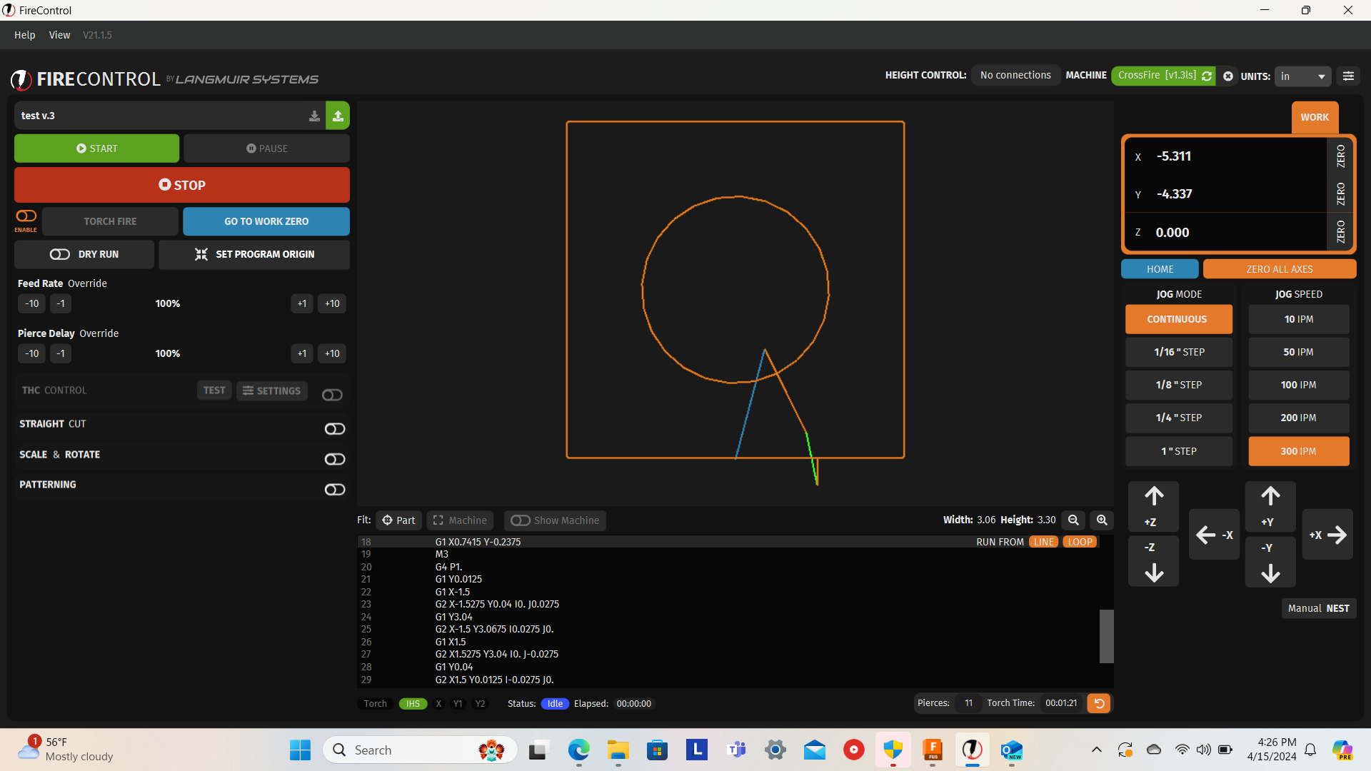
Also something is up with the code from the picture.
Being Line 21 is the first line after a pierce delay or THC off signal there should be a speed code.
it is : G1 Y0.0125 but it should be something like: G1 Y0.0125 F150 so a 150ipm added to the line.
I feel we may have a post processing error. Have you downloaded the FireControl post processor ?
post the full code
2 Likes
i have firecontrol v1.6 loaded into fusion 360 for post processing. i am going to upload th f3d file from this part. i’m sure its a post processing problem cause of the perfect machine simulation in fusion 360 before i post process\convert to gcode
test piece v.2 fd3.f3d (97.7 KB)
this is actually v.2 of my test piece but same thing going on
@OlsonFab can you copy and paste the full text from the g code , the .nc file.
The f3d file would show every other single problem except for the lack of the post processor.
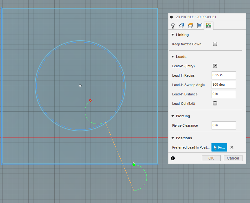
Something to do with the stay down being checked, 900* starting angle, and no lead in / lead out distance?.

I make those changes.

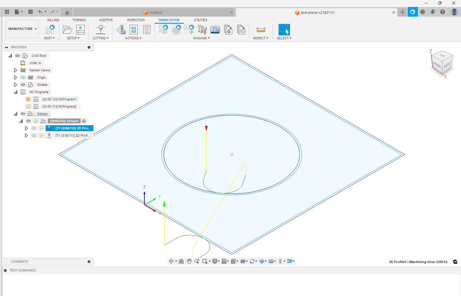
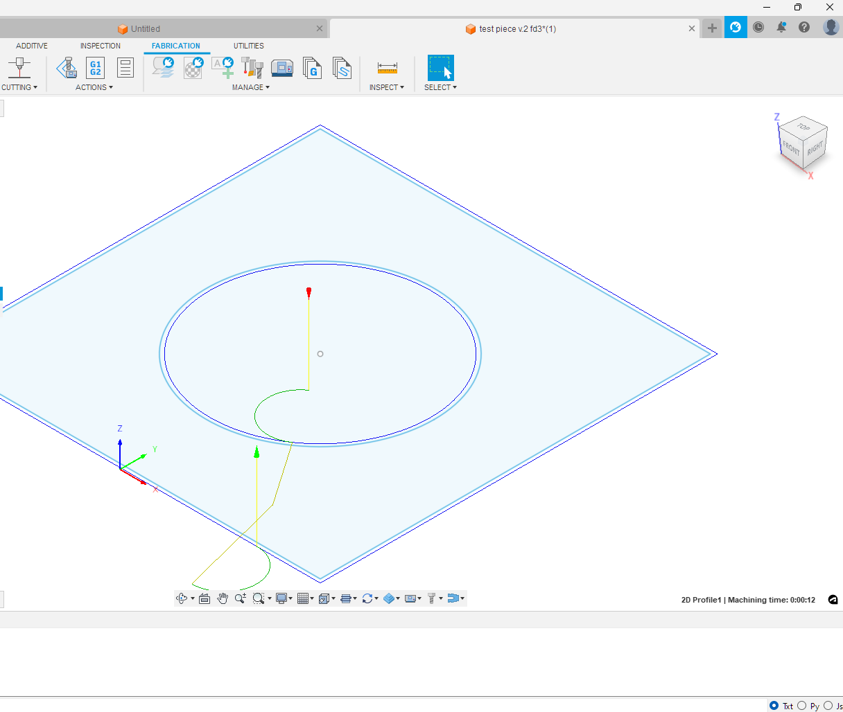
You actually have two tool paths and they both are cutting the same thing with different lead-ins. Here they are with visibility turned on:

You don’t need two different two paths unless you want to do a different sideways compensation for some lines or you need a smaller lead-in to grab discarded contours. Since your contour selection is based on the “sketch”, it will grab everything. That is something you have to watch out with multiple tool paths. When you need the separate actions then you need to be assured that those contours are only included in a single tool path.
Just an aside note: You never need pierce clearance. Just set that to “0”

I notice the dog-leg rapid path is being created by using the option “Keep Nozzle Down.”
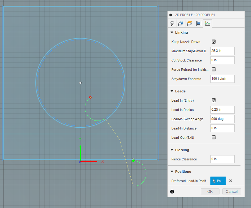
If you remove that option, it will be a straight rapid:
5 Likes
I don’t think i would go with 0 on pierce hight. The recommended hight is 0.15 but on thicker stock it works better the lower you go. However i wouldn’t go lower than 0.08. The reason why they recommended the standoff is to prevent slag from getting on the cutting head. If you’re running thc and get a pice of slag sticking down it will cause the thc to think its lower than it actually is. I have had it happen before and luckily i caught it fairly quickly. One small bb can definitely ruin your day. Just something to watch the closer you set your pierce hight.
1 Like
I think in this case they may be referring to pierce clearance. Pierce clearance which is a linking parameter where it keeps the Pierce hole certain length away from the starting point. This is on top of all the other Linking constraints such as lead in length and lead in radius.
4 Likes
keep nozzle down is needed when i dont have THC because it will put z axis in my g code, correct?
i should have specified on my post that i dont have THC only x and y axis.
1 Like
(v1.6-af)
G90 G94
G17
G20
H0
(2D Profile3)
G0 X0.2648 Y1.0044
M3
G4 P1.
G1 X0.3756 Y0.7803 F100.
G3 X-0.3756 Y2.2997 I-0.3756 J0.7597 F100.
G3 X0.3756 Y0.7803 I0.3756 J-0.7597
M5
G0 Z0.
G1 X0.6416 Y0.242
G1 X0.7415 Y-0.2375
M3
G4 P1.
G1 Y0.0125
G1 X-1.5
G2 X-1.5275 Y0.04 I0. J0.0275
G1 Y3.04
G2 X-1.5 Y3.0675 I0.0275 J0.
G1 X1.5
G2 X1.5275 Y3.04 I0. J-0.0275
G1 Y0.04
G2 X1.5 Y0.0125 I-0.0275 J0.
G1 X0.7415
M5
G0 Z0.
M30
(PS100)