The Mach3 Plasma post does generate .tap extensions. I downloaded and installed it to verify the output.
The .tap file posted above matches what I generated. If the machine has no Z-Axis, the code should work. (Note - I don’t understand the double moves before pierce that occur in several places.)
No. I have to say I am not really with it enough to use the computer. Under the weather with some sort of crude shared by my loving wife: The gift giver!
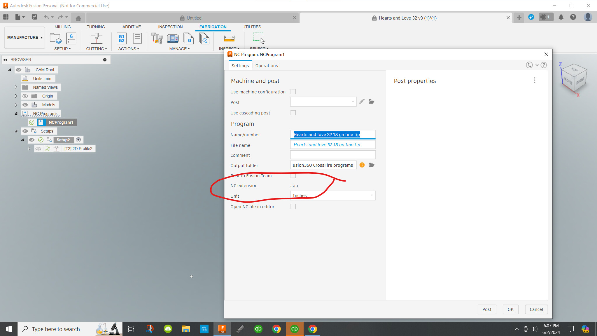
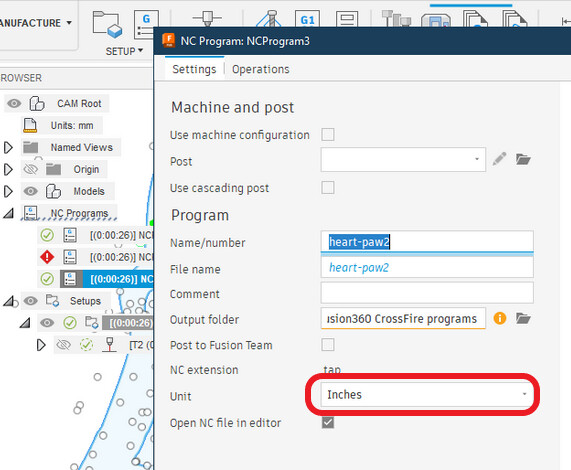
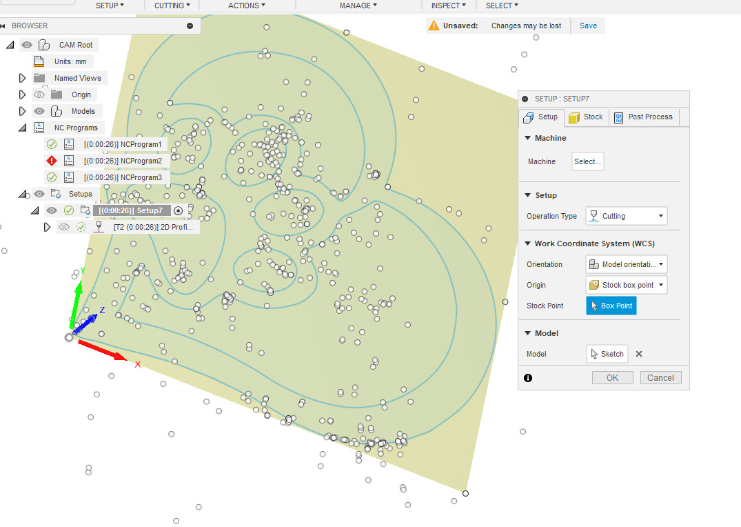
But the problem I have with that screen shot is that no post processor has been selected.
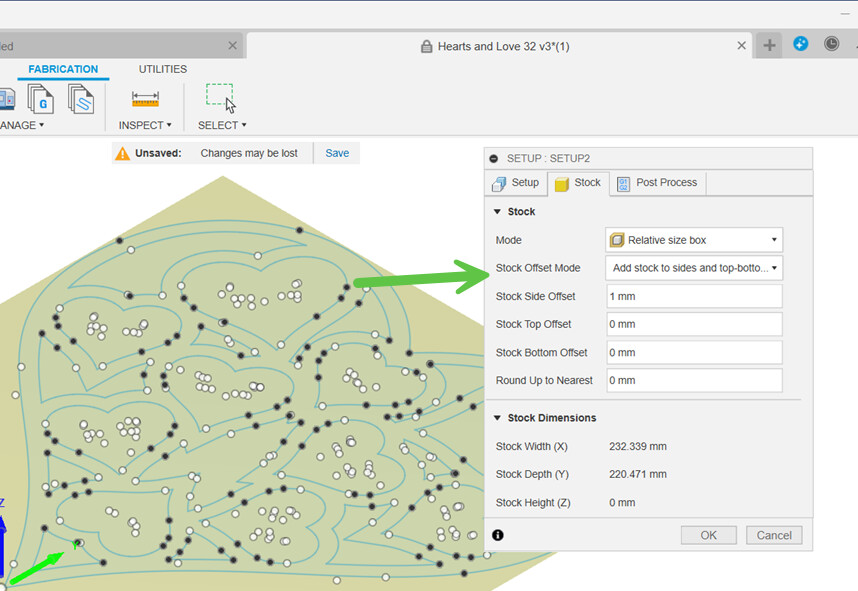
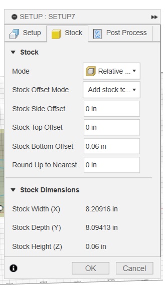
I downloaded your .f3d file. You have the settings in the Setup set incorrectly. “Stock Offset Mode” should be set to “No additional stock”. This is likely the biggest cause of the issue you’re having.
Thank you very much! That was one of my problems. I’ll have to make 2 saves with half of the cuts on one and half on the second? Or I’ll have to buy the full version
Thank you very much for your help!! I noted all the settings and will make sure they’re the same for the next one. Now my problem is too many lines for the free version of mach 3. Before I buy the full version I’m going to try 2 saves with half of the cuts on one and the other half on the second. My plasma cutter is giving me problems now, so I’ve got some troubleshooting to do.
You might as well bite the bullet, it’s not that expensive and your system is pretty close to worthless without it. Your only alternative is to replace the Main Controller board with one that doesn’t require Mach3, but that’s more expensive and complex than going with a licensed version of Mach3.
One think to verify - The Smoothing setting in Fusion. I believe you had it left to the default of 0.0004". I usually change to 0.001". This reduced your code length by ~50%. (Fusion was generating many straight line cuts instead of arcs.) You may wish to play with setting it to 0.002" to see if your code reduces further. (# of lines.) Since most of what I’ve seen, dimensional accuracy is not as important as artistic merit with your designs, so please verify prior to cutting.
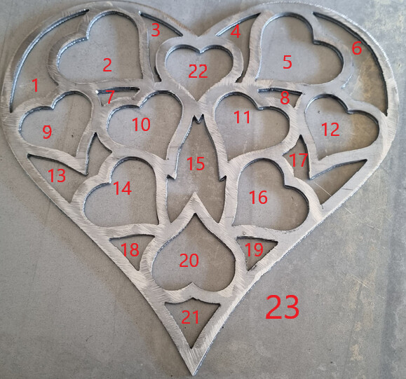
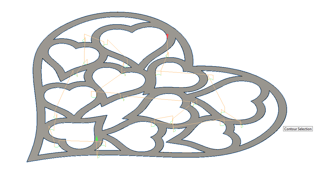
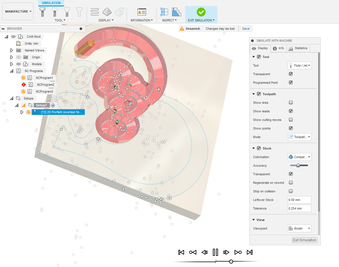
Thank you so much for all your help simsworx! I put my smoothing tolerance to .09mm to get the code down to less than 500 lines. Next time I might try one cut of the hearts and another cut with the other shapes and the outline. Under geometry you only have 1 face contour. When I did it I got 23 closed chains. How did you do it differently?
Every time the torch is directed to move and cut, that is one contour.
You got 23 individual contours because you clicked on each contour. The secret between picking the “face” and the contour is that you want to zoom up close enough that the mouse is not confused of whether you are clicking on the face or the actual contour. You don’t want to click on any contour…just the face. Fusion will then figure out all of the contours to be cut.
heart-paw.dxf (39.7 KB) heart-paw2.tap (28.2 KB) heart-paw v3.f3d (387.5 KB)
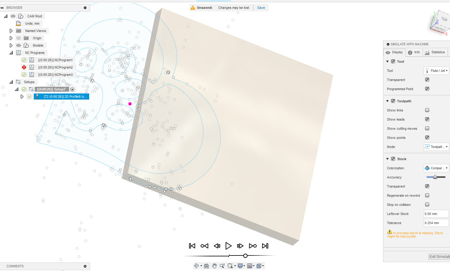
I don’t get it. I started a new piece to cut. I used the same settings as the hearts and love, as a guide, but I can’t seem to get rid of the holder+stock error. When I ignored it and sent it to post, the path in mach 3 looks nothing like the simulated cut in fusion.
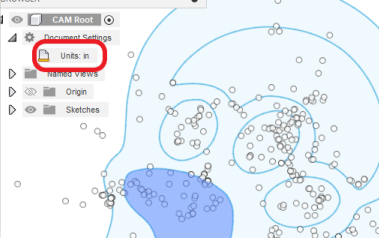
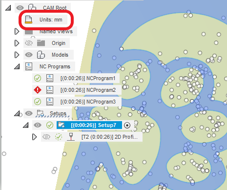
But I hesitate to help you further. I really recommended that you draw a simple design of your own. Perhaps a box with a heart shape. Make sure your units are consistent and take it to manufacturing. You need to get the basics down instead of trying to cram a drawing into a perceived formula. You are going to frustrate the heck out of yourself. You need to be learning the nuts and bolts of how the drawing goes from design to CAM to post processing and then to Mach 3.
One of the other things noticed, in addition to what @ChelanJim mentioned, relates directly to the stock. By not extruding your design, the sketch lies directly on the Z Axis plane. When stock is defined in Setup, stock thickness will default to +Z Axis, placing your sketch / design under the stock. Change this by setting 0 additional Top Stock and adding a Bottom Stock Value.