Contraption1.zip (774.8 KB)
Need help figuring out how to make gears move together and only by moving handle attached to small gear…small gear/ handle move as one and handle about 90 degree movement from right horizontal to vertical position… and the slots slide while moving shaft L to R as well. Anyone have this level of knowledge? Making sure I make all required mods before wasting metal cutting out wrong parts.
PS: Fusion will not export DXF without subscription is beyond words…it literally can be done free online or export svg and then convert with any other CAD…even free ones!
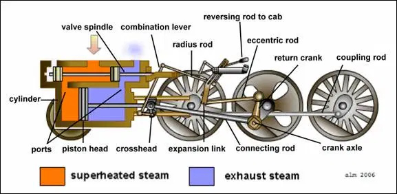
real neat drawing…looking at it AutoCAD…it looks like something based of the old steam train propulsion wheel drive
I believe your small week deeds to have the shaft off center in order to let the slide rotation to complete a full circle
This is an art thing… absolutely has no load or work associated with the gears… Just want them to turn while handle is moved. This is a toilet paper holder… just for the fun of it. The shaft moving from left to right and back is all that’s important… and I’m already making mods to the linkage so the bearings ride in the slots so nothing “hangs up” while in motion. Will be adding pressed on bearings on the shaft that interacts with both slots and to mount the gears so everything is smooth moving.
holy crap…pun intended…
regardless of the load or no load…but I believe the physics are the same…you need to be off center of one wheel
Gears are just turning with motion of the handle. The shaft that slides is linear… which is accommodated by the slots… which the one slot is to account for the radial movement of the handle. The other slot keeps the shaft square while sliding. No matter if it works or doesn’t work in real life… just want model to turn gears and slide shaft side to side. Having the model “working” is what helps figure out the changes I need to make before cutting the metal up.
use the crossfire to draw it out on a piece of cardboard…cut it out…try it…
I have done that a few times for signs for full size demo’s for clients.
cardboard is easier and cheaper than metal…
That’s one way…was hoping to accomplish this in F360. Kind of defeats the purpose of CAD when doing things the way of before CAD.
1 Like
You did one hell of a job doing that drawing . It is pretty dam great.
But sometimes even prototypes have to be built to work out the bugs.
Was able to get the large gear rotating but having trouble getting small gear and handle tied together and rotate…while it turns the large gear and slides shaft LtoR. Realized the DXF does nothing to help with joints in F360… not sure how/ what to upload for help.
Maybe a public F360 link… https://a360.co/2Jldl6z
Here is file… finally have a working model… Works well.
Its F360 file… change ext.Contrap2V.dxf (2.2 MB)