Ok guys - first off , Langmuir sent me a nes sd card and the machine runs perfect. Yee haa. Ok now this one gets in to user and if anyone can post some lings on toutorls on this - that would help. So here is my hang up and i dont know if its somthing i am missing in fusion or what. So i design a part and it had lets say 2 90 degree bends. well what you look at the flat pattern on your drawing sheet with dimention - it will referance one edge - lets say bend line 1 is 2” from the edge then bend 2 is actualy 2” away from that - but the drawing will show 4” from the edge. this is just an example - the actual numbers would be like 2.125 then 4.628 ( taking in all the K factors. well the first bend well be spot in when setting the back gage - but after that it will be wrong of corse becusr the first bend is already done. I guess you could just do the math - But i guess that sorta defets the porpose of doing all this in a way. Any one have any insite on this ? I know its just learing but this one I can not find any help with learing it.
Can you just go off the other edge? or do you have more than 2 bends?
Yout could - but when i am trying to bend an accurate chanel - whats when i keep running in to the huckup. if i went off the other side and the piece was not excat than the chanel dimention would be wrong - tried that - I know this is weird. But i want to learn it. I know if i were to just keep doing test bends and figure out the actual end result then find the math to fusions drawings - than that would remain a constant for each material thickness - but that would only be 90 degree - every time you had a different angle that would change. Does this all make sence
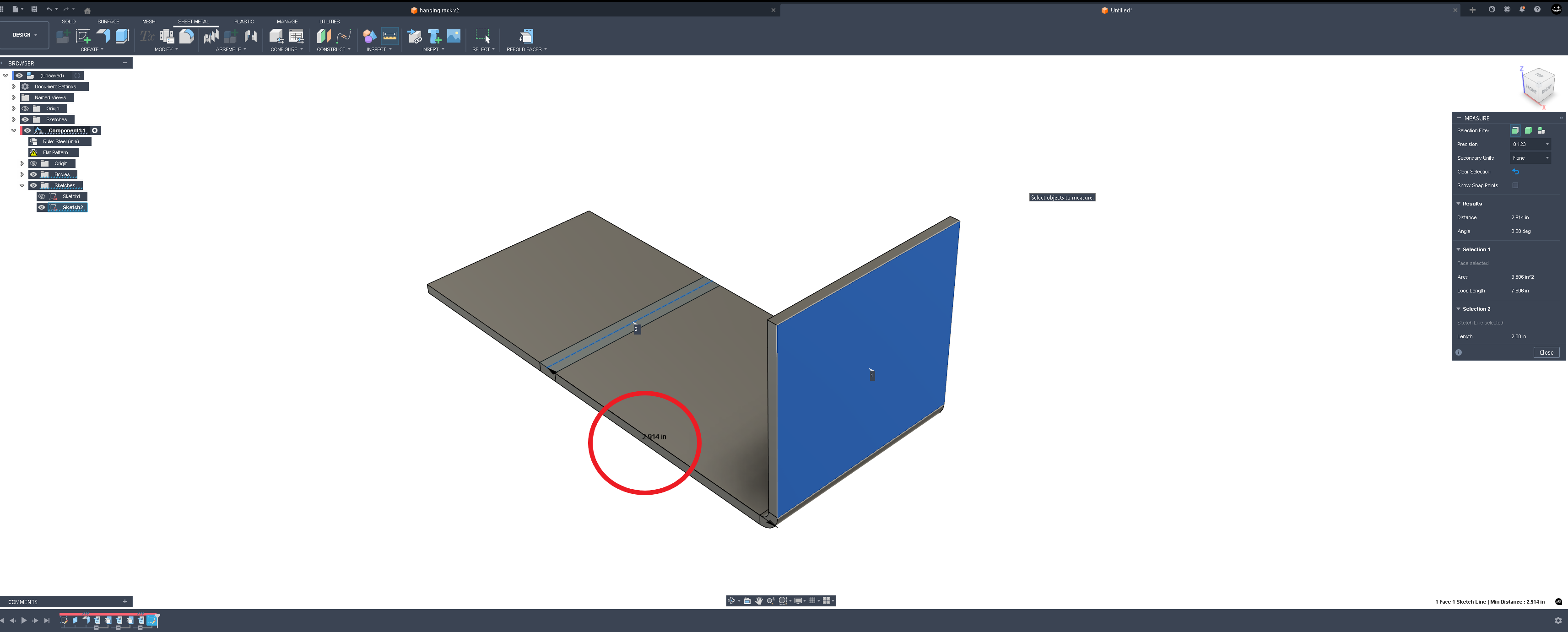
Then use the unbend tool to unbend the 2nd bend.

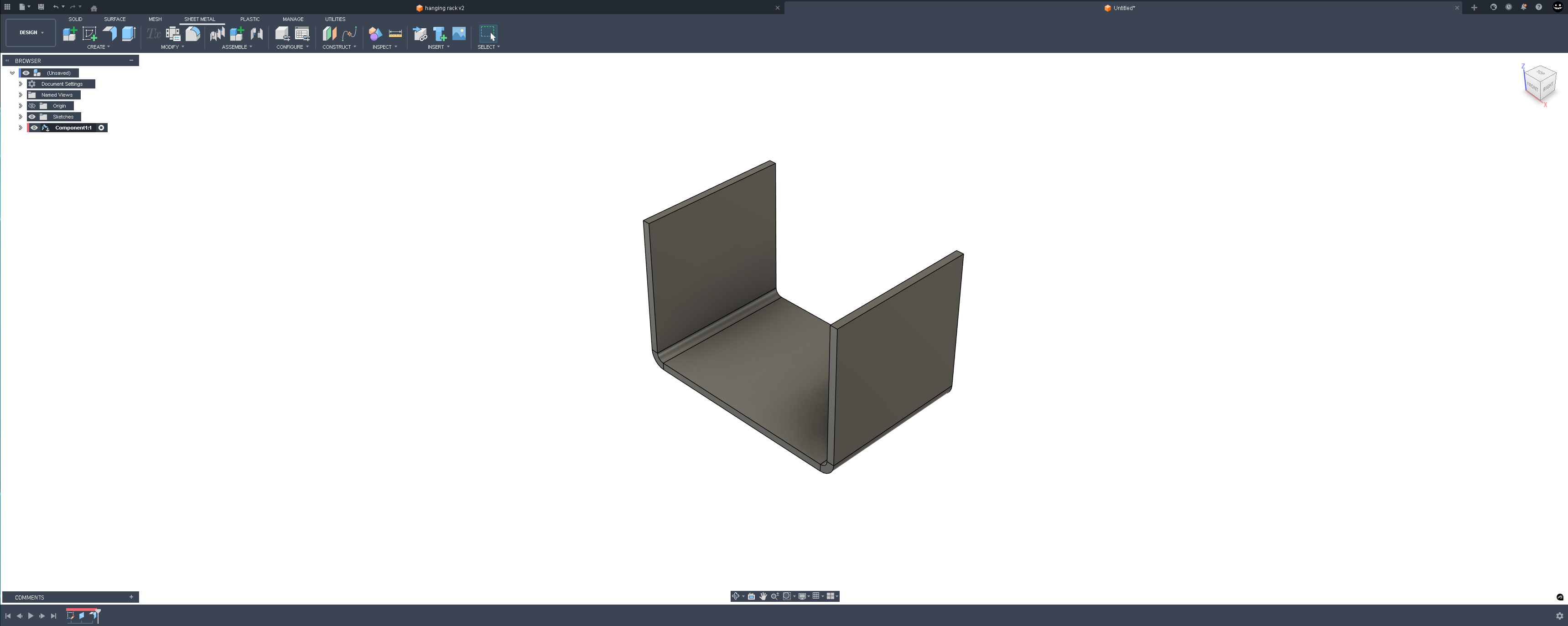
Create a sketch to represent the central line of the second bend

use the measure tool to measure from the face of the first bend to the center line to the second
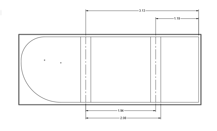
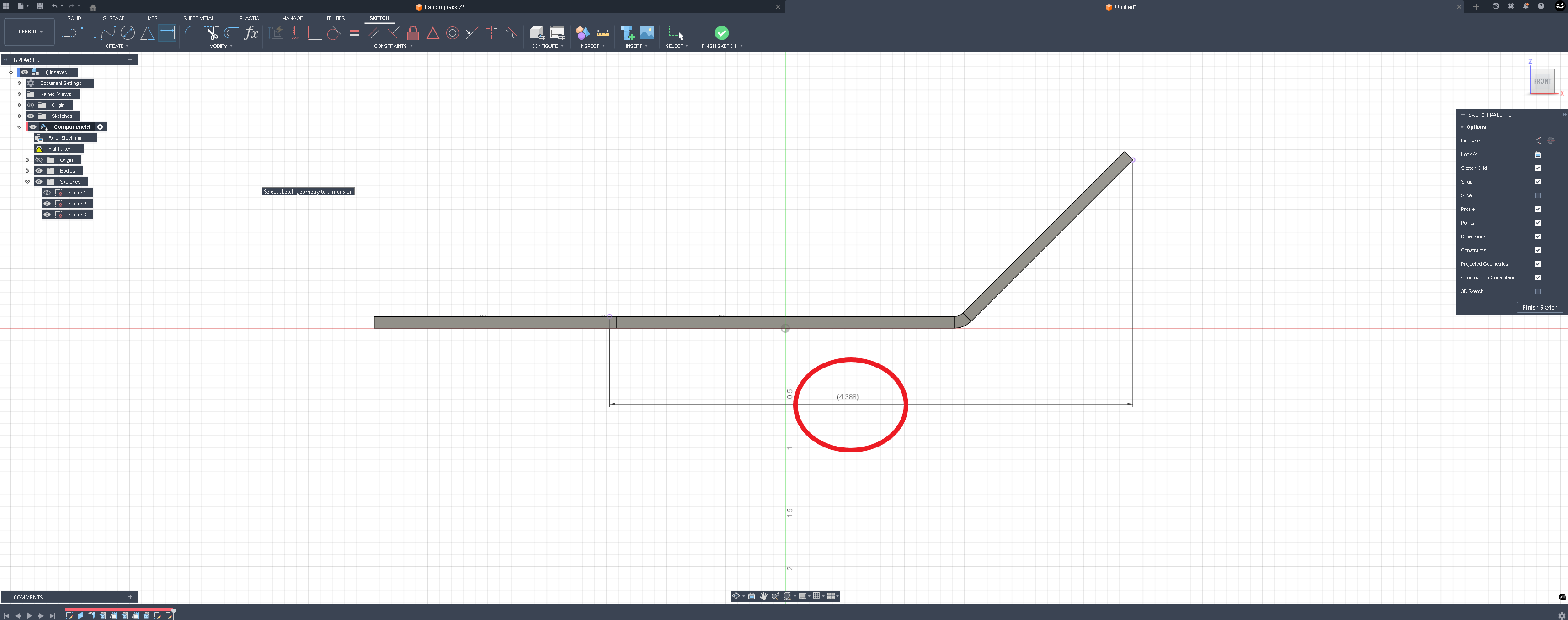
where it will actually get tricky is if your bends are not 90° but let’s say that your fingers will reference the very outermost point of the part being bent. here’s the same example with 45° flanges.
Now use the unbend tool and make a reference sketch the same as you would in the first example.
But instead of the measure tool you have to use the dimension tool in the sketch environment to obtain this next measurement.
The trick now getting the fingers to reference that outermost edge before bending.
These two examples are how I’ve done it and had some success with it in the past. I don’t think fusion has an easy button for this function but if it does hopefully somebody can post that here.
At least this way you’re not really doing any math. you’re referencing geometry straight off the drawing.
I guess it depends on how close you are trying to hold your tolerances. If you don’t cut the part to the correct size to start, then how can it come out right no matter how you bend it? Maybe I don’t under stand what you are trying to do.
Maybe I am not doing it correctly but here is what i do.
I take the dimension shown in this screen shot and use that to set my back gauge
That seems to work for me.

yes that’s how you would do it for the first bend and you could just flip the part and then do the other bend. But what the OP is asking is how to bend that first bend and then bend the second bend with the first bend against the fingers.
Yes I get that.
I was just pointing out an easy way to do it differently.
I guess I don’t see any advantage to do it that way.
Maybe I just don’t get it, that would not be anything new🤣